Diagnostic Mode
Fragment manuala — str. 540–547
📋 Tekst do skopiowania / wyszukiwania
FUEL INJECTION SYSTEM
5. Erase the malfunction history in the diagnos- The engine operation is not normal but the
tic mode. Refer to “Sensor operation table engine trouble warning light does not come
(Diagnostic code No. 62)”. on.
NOTE: 1. Check the operation of following sensors and
Turning the main switch to “OFF” will not erase actuators in the Diagnostic mode. Refer to
the malfunction history. “Sensor operation table” and “Actuator oper-
ation table”.
01: Throttle position sensor (throttle angle)
30: Cylinders-#1/#4 ignition coil
31: Cylinders-#2/#3 ignition coil
36: Injector #1
37: Injector #2
38: Injector #3
39: Injector #4
48: Air induction system solenoid
If a malfunction is detected in the sensors or
actuators, repair or replace all faulty parts.
If no malfunction is detected in the sensors
and actuators, check and repair inner parts of
the engine.
EAS27410
DIAGNOSTIC MODE
Setting the diagnostic mode
1. Turn the main switch to “OFF”.
2. Disconnect the wire harness coupler from the fuel pump.
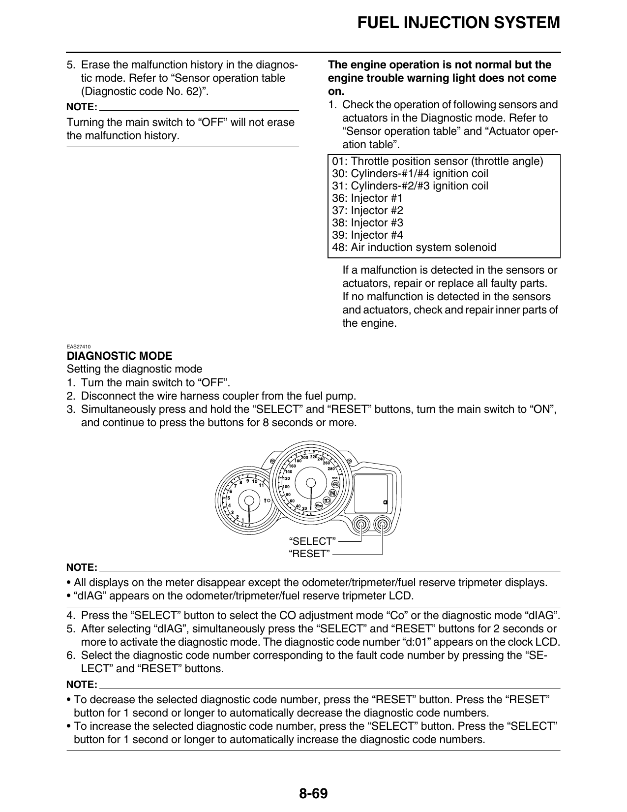
3. Simultaneously press and hold the “SELECT” and “RESET” buttons, turn the main switch to “ON”,
and continue to press the buttons for 8 seconds or more.
“SELECT”
“RESET”
NOTE:
• All displays on the meter disappear except the odometer/tripmeter/fuel reserve tripmeter displays.
• “dIAG” appears on the odometer/tripmeter/fuel reserve tripmeter LCD.
4. Press the “SELECT” button to select the CO adjustment mode “Co” or the diagnostic mode “dIAG”.
5. After selecting “dIAG”, simultaneously press the “SELECT” and “RESET” buttons for 2 seconds or
more to activate the diagnostic mode. The diagnostic code number “d:01” appears on the clock LCD.
6. Select the diagnostic code number corresponding to the fault code number by pressing the “SE-
LECT” and “RESET” buttons.
NOTE:
• To decrease the selected diagnostic code number, press the “RESET” button. Press the “RESET”
button for 1 second or longer to automatically decrease the diagnostic code numbers.
• To increase the selected diagnostic code number, press the “SELECT” button. Press the “SELECT”
button for 1 second or longer to automatically increase the diagnostic code numbers.
8-69
FUEL INJECTION SYSTEM
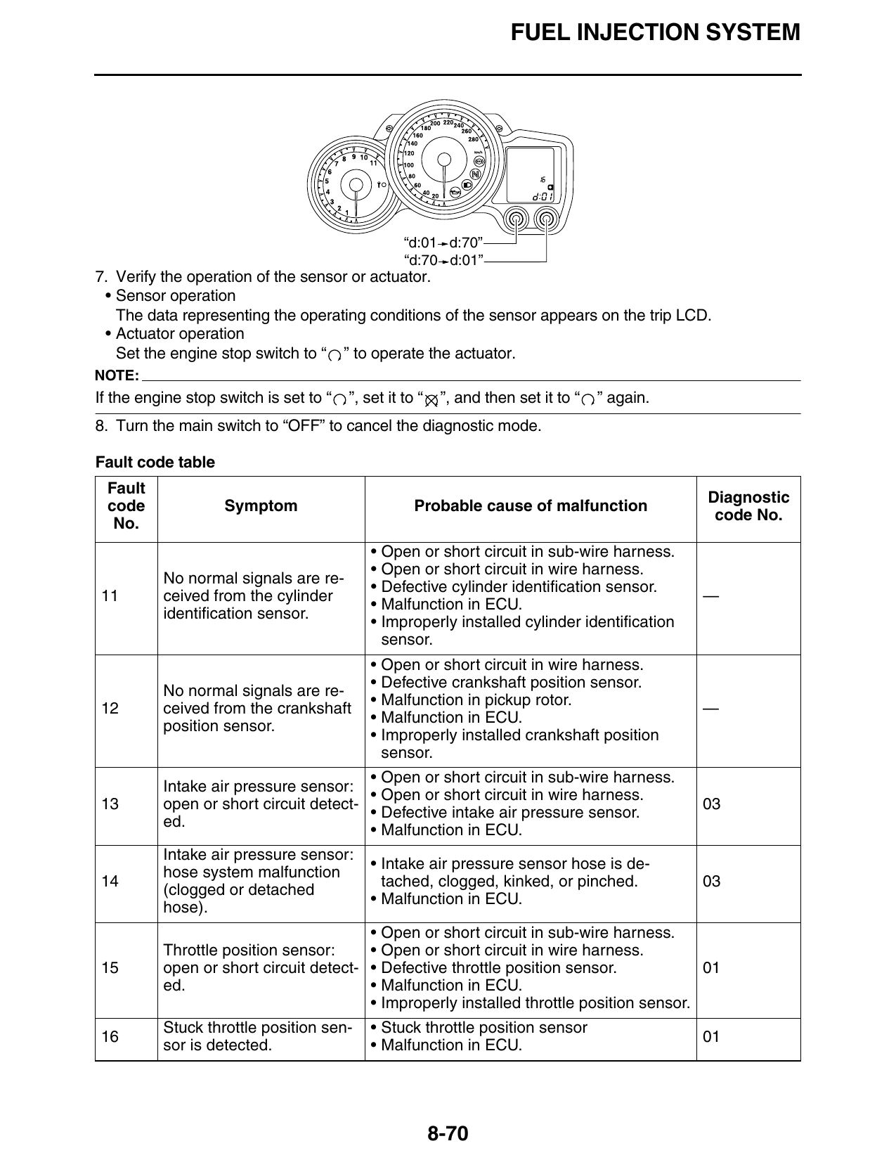
“d:01 d:70”
“d:70 d:01”
7. Verify the operation of the sensor or actuator.
• Sensor operation
The data representing the operating conditions of the sensor appears on the trip LCD.
• Actuator operation
Set the engine stop switch to “ ” to operate the actuator.
NOTE:
If the engine stop switch is set to “ ”, set it to “ ”, and then set it to “ ” again.
8. Turn the main switch to “OFF” to cancel the diagnostic mode.
Fault code table
Fault
Diagnostic
code Symptom Probable cause of malfunction
code No.
No.
• Open or short circuit in sub-wire harness.
• Open or short circuit in wire harness.
No normal signals are re-
• Defective cylinder identification sensor.
11 ceived from the cylinder —
• Malfunction in ECU.
identification sensor.
• Improperly installed cylinder identification
sensor.
• Open or short circuit in wire harness.
• Defective crankshaft position sensor.
No normal signals are re-
• Malfunction in pickup rotor.
12 ceived from the crankshaft —
• Malfunction in ECU.
position sensor.
• Improperly installed crankshaft position
sensor.
• Open or short circuit in sub-wire harness.
Intake air pressure sensor:
• Open or short circuit in wire harness.
13 open or short circuit detect- 03
• Defective intake air pressure sensor.
ed.
• Malfunction in ECU.
Intake air pressure sensor:
• Intake air pressure sensor hose is de-
hose system malfunction
14 tached, clogged, kinked, or pinched. 03
(clogged or detached
• Malfunction in ECU.
hose).
• Open or short circuit in sub-wire harness.
Throttle position sensor: • Open or short circuit in wire harness.
15 open or short circuit detect- • Defective throttle position sensor. 01
ed. • Malfunction in ECU.
• Improperly installed throttle position sensor.
Stuck throttle position sen- • Stuck throttle position sensor
16 01
sor is detected. • Malfunction in ECU.
8-70
FUEL INJECTION SYSTEM
Fault
Diagnostic
code Symptom Probable cause of malfunction
code No.
No.
• Open or short circuit in front cowling wire
A break or disconnection of harness.
19 the black/red lead of the • Open or short circuit in wire harness. 20
ECU is detected. • Malfunction in ECU.
• Defective relay unit (diode).
• Open or short circuit in wire harness.
Coolant temperature sen- • Defective coolant temperature sensor.
21 sor: open or short circuit • Malfunction in ECU. 06
detected. • Improperly installed coolant temperature
sensor.
• Open or short circuit in wire harness.
Intake air temperature sen- • Defective intake temperature sensor.
22 sor: open or short circuit • Malfunction in ECU. 05
detected. • Improperly installed intake air temperature
sensor.
• Open or short circuit in sub-wire harness.
• Open or short circuit in front cowling wire
harness.
No normal signal is re- • Open or short circuit in wire harness.
24 ceived from the O2 sensor. —
• Defective O2 sensor.
• Malfunction in ECU.
• Improperly installed O2 sensor.
Latch up detected. • The vehicle has overturned.
No normal signal is re- • Defective lean angle sensor.
30 08
ceived from the lean angle • Malfunction in ECU.
sensor. • Improperly installed lean angle sensor.
• Open or short circuit in sub-wire harness.
• Open or short circuit in front cowling wire
harness.
The amount of air-fuel ratio • Open or short circuit in wire harness.
feedback compensation is • Fuel pressure too low.
31 maintained continuously in • Clogged injectors. 01
the vicinity of the upper lim- Defective O2 sensor (unable to output a rich
•
it (lean air-fuel ratio). signal).
• Malfunction in ECU.
• Malfunction in other areas of the fuel sys-
tem.
• Open or short circuit in sub-wire harness.
• Open or short circuit in front cowling wire
harness.
• Open or short circuit in wire harness.
The amount of air-fuel ratio • Fuel pressure too high.
feedback compensation is • Faulty injectors (excessive injection vol-
32 maintained continuously in ume). 01
the vicinity of the lower limit • Defective O sensor (unable to output a
(rich air-fuel ratio). 2
lean signal).
• Malfunction in ECU.
• Malfunction in other areas of the fuel sys-
tem.
8-71
FUEL INJECTION SYSTEM
Fault
Diagnostic
code Symptom Probable cause of malfunction
code No.
No.
• Open or short circuit in front cowling wire
Malfunction detected in the harness.
33 primary wire of the cylin- • Open or short circuit in wire harness. 30
ders-#1/#4 ignition coil. • Malfunction in cylinders-#1/#4 ignition coil.
• Malfunction in ECU.
• Open or short circuit in front cowling wire
Malfunction detected in the harness.
34 primary wire of the cylin- • Open or short circuit in wire harness. 31
ders-#2/#3 ignition coil. • Malfunction in cylinders-#2/#3 ignition coil.
• Malfunction in ECU.
• Open or short circuit in front cowling wire
harness.
Lean angle sensor: open or
41 • Open or short circuit in wire harness. 08
short circuit detected.
• Defective lean angle sensor.
• Malfunction in ECU.
• Open or short circuit in ABS wire harness.
• Open or short circuit in front cowling wire
No normal signals are re- harness.
ceived from the rear wheel • Open or short circuit in wire harness.
sensor. • Defective rear wheel sensor.
Open or short circuit is de- • Malfunction in rear wheel sensor detected.
tected in the neutral circuit • Defective gear position switch. (FJR13A) 07
of the gear position switch. • Defective neutral switch. (FJR13AE) 21
(FJR13A) • Malfunction in the engine side of the gear
Open or short circuit is de- position switch. (FJR13A)
tected in the neutral switch. • Malfunction in the engine side of the neutral
(FJR13AE) switch. (FJR13AE)
• Malfunction in ECU.
• Malfunction in ABS ECU.
The ECU is unable to moni- • Open or short circuit in front cowling wire
tor the battery voltage (an harness.
43 09
open or short circuit in the • Open or short circuit in wire harness.
line to the ECU). • Malfunction in ECU.
An error is detected while
• Malfunction in ECU. (The CO adjustment
reading or writing on EE-
44 value is not properly written on or read from 60
PROM (CO adjustment val-
the internal memory).
ue).
Power supply to the fuel in-
Malfunction in the charging system. Refer to
46 jection system is not nor- —
“CHARGING SYSTEM” on page 8-29.
mal.
Faulty ECU memory.
(When this malfunction is • Malfunction in ECU. (The program and data
50 detected in the ECU, the are not properly written on or read from the —
fault code number might internal memory.)
not appear on the meter.)
8-72
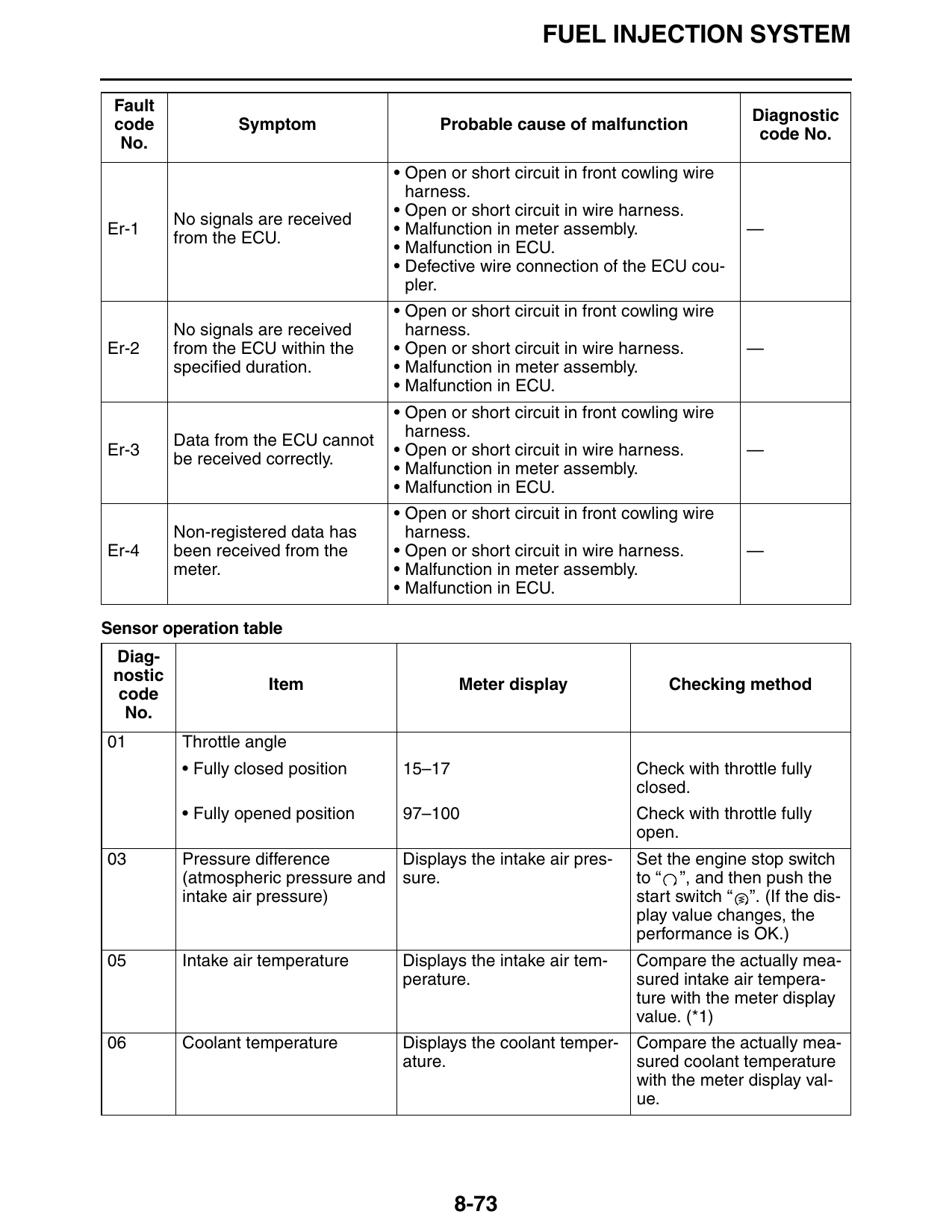
FUEL INJECTION SYSTEM
Fault
Diagnostic
code Symptom Probable cause of malfunction
code No.
No.
• Open or short circuit in front cowling wire
harness.
• Open or short circuit in wire harness.
No signals are received
Er-1 • Malfunction in meter assembly. —
from the ECU.
• Malfunction in ECU.
• Defective wire connection of the ECU cou-
pler.
• Open or short circuit in front cowling wire
No signals are received harness.
Er-2 from the ECU within the • Open or short circuit in wire harness. —
specified duration. • Malfunction in meter assembly.
• Malfunction in ECU.
• Open or short circuit in front cowling wire
harness.
Data from the ECU cannot
Er-3 • Open or short circuit in wire harness. —
be received correctly.
• Malfunction in meter assembly.
• Malfunction in ECU.
• Open or short circuit in front cowling wire
Non-registered data has harness.
Er-4 been received from the • Open or short circuit in wire harness. —
meter. • Malfunction in meter assembly.
• Malfunction in ECU.
Sensor operation table
Diag-
nostic
Item Meter display Checking method
code
No.
01 Throttle angle
• Fully closed position 15–17 Check with throttle fully
closed.
• Fully opened position 97–100 Check with throttle fully
open.
03 Pressure difference Displays the intake air pres- Set the engine stop switch
(atmospheric pressure and sure. to “ ”, and then push the
intake air pressure) start switch “ ”. (If the dis-
play value changes, the
performance is OK.)
05 Intake air temperature Displays the intake air tem- Compare the actually mea-
perature. sured intake air tempera-
ture with the meter display
value. (*1)
06 Coolant temperature Displays the coolant temper- Compare the actually mea-
ature. sured coolant temperature
with the meter display val-
ue.
8-73
FUEL INJECTION SYSTEM
Diag-
nostic
Item Meter display Checking method
code
No.
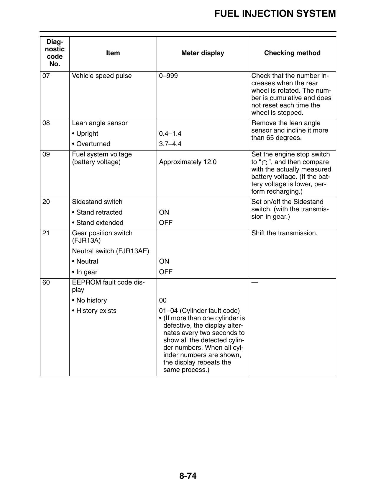
07 Vehicle speed pulse 0–999 Check that the number in-
creases when the rear
wheel is rotated. The num-
ber is cumulative and does
not reset each time the
wheel is stopped.
08 Lean angle sensor Remove the lean angle
• Upright 0.4–1.4 sensor and incline it more
than 65 degrees.
• Overturned 3.7–4.4
09 Fuel system voltage Set the engine stop switch
(battery voltage) Approximately 12.0 to “ ”, and then compare
with the actually measured
battery voltage. (If the bat-
tery voltage is lower, per-
form recharging.)
20 Sidestand switch Set on/off the Sidestand
• Stand retracted ON switch. (with the transmis-
sion in gear.)
• Stand extended OFF
21 Gear position switch Shift the transmission.
(FJR13A)
Neutral switch (FJR13AE)
• Neutral ON
• In gear OFF
60 EEPROM fault code dis- —
play
• No history 00
• History exists 01–04 (Cylinder fault code)
• (If more than one cylinder is
defective, the display alter-
nates every two seconds to
show all the detected cylin-
der numbers. When all cyl-
inder numbers are shown,
the display repeats the
same process.)
8-74
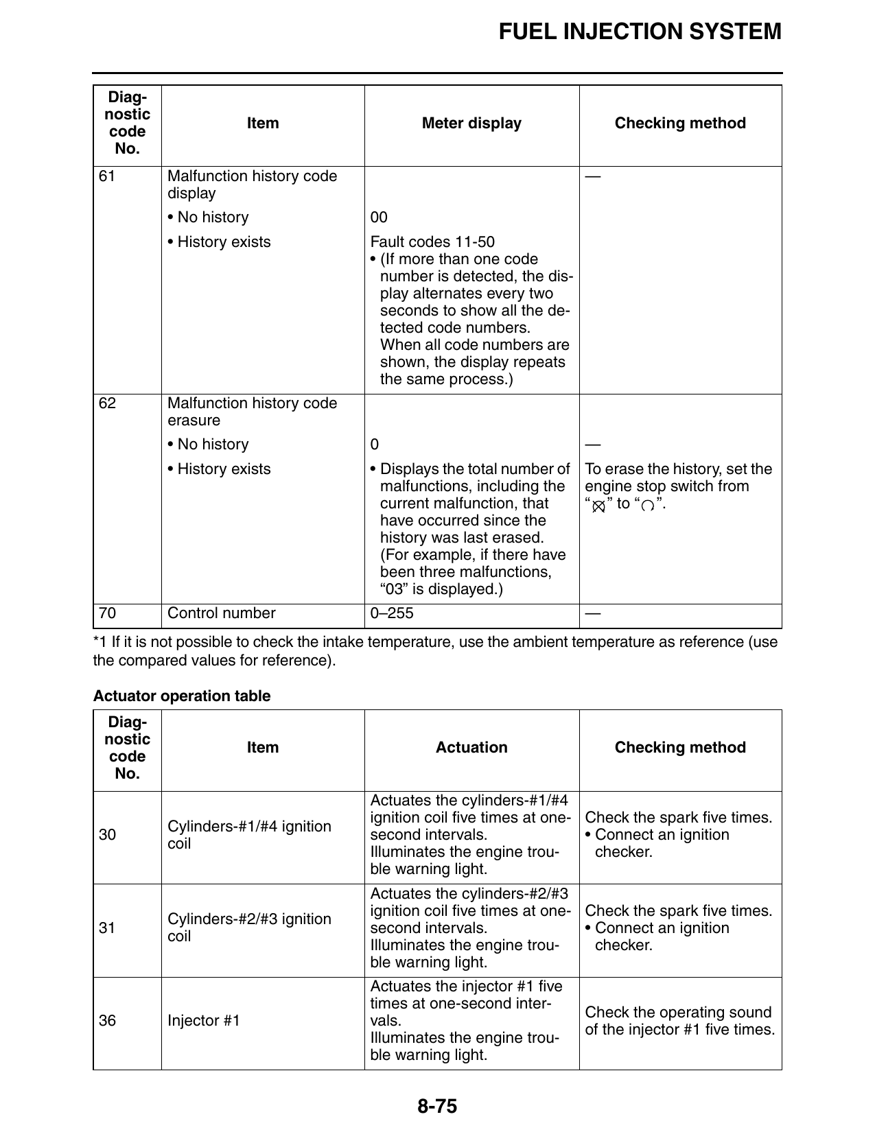
FUEL INJECTION SYSTEM
Diag-
nostic
Item Meter display Checking method
code
No.
61 Malfunction history code —
display
• No history 00
• History exists Fault codes 11-50
• (If more than one code
number is detected, the dis-
play alternates every two
seconds to show all the de-
tected code numbers.
When all code numbers are
shown, the display repeats
the same process.)
62 Malfunction history code
erasure
• No history 0 —
• History exists • Displays the total number of To erase the history, set the
malfunctions, including the engine stop switch from
current malfunction, that “ ” to “ ”.
have occurred since the
history was last erased.
(For example, if there have
been three malfunctions,
“03” is displayed.)
70 Control number 0–255 —
*1 If it is not possible to check the intake temperature, use the ambient temperature as reference (use
the compared values for reference).
Actuator operation table
Diag-
nostic
Item Actuation Checking method
code
No.
Actuates the cylinders-#1/#4
ignition coil five times at one- Check the spark five times.
Cylinders-#1/#4 ignition
30 second intervals. • Connect an ignition
coil
Illuminates the engine trou- checker.
ble warning light.
Actuates the cylinders-#2/#3
ignition coil five times at one- Check the spark five times.
Cylinders-#2/#3 ignition
31 second intervals. • Connect an ignition
coil
Illuminates the engine trou- checker.
ble warning light.
Actuates the injector #1 five
times at one-second inter-
Check the operating sound
36 Injector #1 vals.
of the injector #1 five times.
Illuminates the engine trou-
ble warning light.
8-75
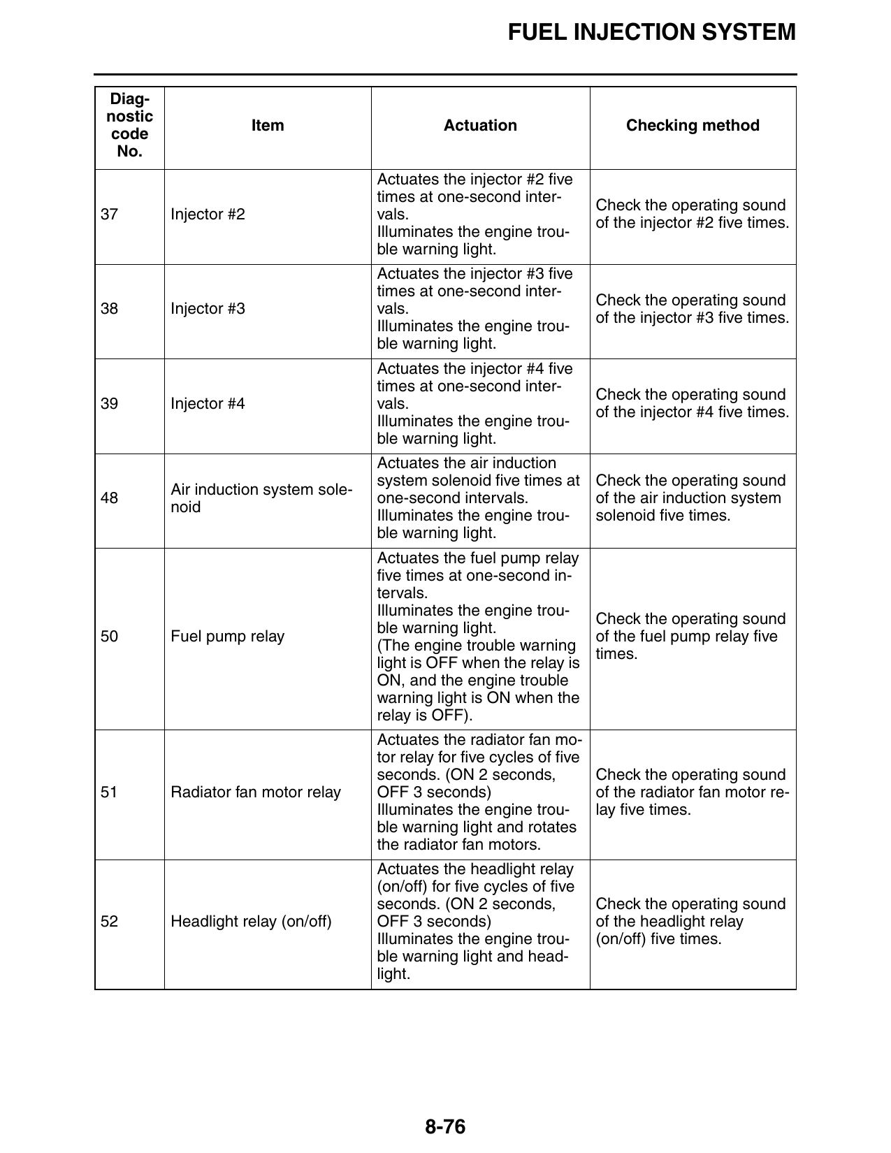
FUEL INJECTION SYSTEM
Diag-
nostic
Item Actuation Checking method
code
No.
Actuates the injector #2 five
times at one-second inter-
Check the operating sound
37 Injector #2 vals.
of the injector #2 five times.
Illuminates the engine trou-
ble warning light.
Actuates the injector #3 five
times at one-second inter-
Check the operating sound
38 Injector #3 vals.
of the injector #3 five times.
Illuminates the engine trou-
ble warning light.
Actuates the injector #4 five
times at one-second inter-
Check the operating sound
39 Injector #4 vals.
of the injector #4 five times.
Illuminates the engine trou-
ble warning light.
Actuates the air induction
system solenoid five times at Check the operating sound
Air induction system sole-
48 one-second intervals. of the air induction system
noid
Illuminates the engine trou- solenoid five times.
ble warning light.
Actuates the fuel pump relay
five times at one-second in-
tervals.
Illuminates the engine trou-
Check the operating sound
ble warning light.
50 Fuel pump relay of the fuel pump relay five
(The engine trouble warning
times.
light is OFF when the relay is
ON, and the engine trouble
warning light is ON when the
relay is OFF).
Actuates the radiator fan mo-
tor relay for five cycles of five
seconds. (ON 2 seconds, Check the operating sound
51 Radiator fan motor relay OFF 3 seconds) of the radiator fan motor re-
Illuminates the engine trou- lay five times.
ble warning light and rotates
the radiator fan motors.
Actuates the headlight relay
(on/off) for five cycles of five
seconds. (ON 2 seconds, Check the operating sound
52 Headlight relay (on/off) OFF 3 seconds) of the headlight relay
Illuminates the engine trou- (on/off) five times.
ble warning light and head-
light.
8-76