Troubleshooting Details
Fragment manuala — str. 548–571

📋 Tekst do skopiowania / wyszukiwania
FUEL INJECTION SYSTEM
Diag-
nostic
Item Actuation Checking method
code
No.
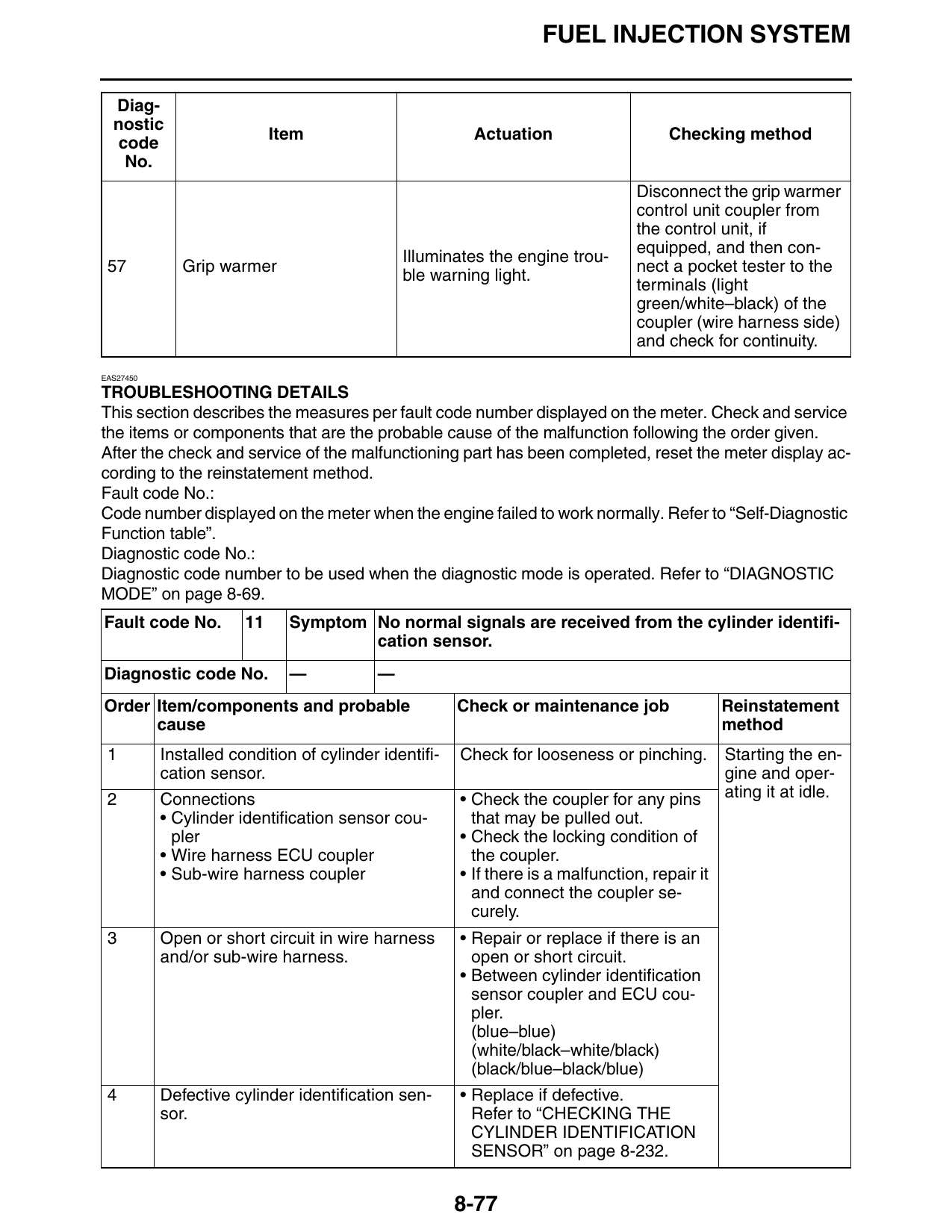
Disconnect the grip warmer
control unit coupler from
the control unit, if
equipped, and then con-
Illuminates the engine trou-
57 Grip warmer nect a pocket tester to the
ble warning light.
terminals (light
green/white–black) of the
coupler (wire harness side)
and check for continuity.
EAS27450
TROUBLESHOOTING DETAILS
This section describes the measures per fault code number displayed on the meter. Check and service
the items or components that are the probable cause of the malfunction following the order given.
After the check and service of the malfunctioning part has been completed, reset the meter display ac-
cording to the reinstatement method.
Fault code No.:
Code number displayed on the meter when the engine failed to work normally. Refer to “Self-Diagnostic
Function table”.
Diagnostic code No.:
Diagnostic code number to be used when the diagnostic mode is operated. Refer to “DIAGNOSTIC
MODE” on page 8-69.
Fault code No. 11 Symptom No normal signals are received from the cylinder identifi-
cation sensor.
Diagnostic code No. — —
Order Item/components and probable Check or maintenance job Reinstatement
cause method
1 Installed condition of cylinder identifi- Check for looseness or pinching. Starting the en-
cation sensor. gine and oper-
2 Connections • Check the coupler for any pins ating it at idle.
• Cylinder identification sensor cou- that may be pulled out.
pler • Check the locking condition of
• Wire harness ECU coupler the coupler.
• Sub-wire harness coupler • If there is a malfunction, repair it
and connect the coupler se-
curely.
3 Open or short circuit in wire harness • Repair or replace if there is an
and/or sub-wire harness. open or short circuit.
• Between cylinder identification
sensor coupler and ECU cou-
pler.
(blue–blue)
(white/black–white/black)
(black/blue–black/blue)
4 Defective cylinder identification sen- • Replace if defective.
sor. Refer to “CHECKING THE
CYLINDER IDENTIFICATION
SENSOR” on page 8-232.
8-77
FUEL INJECTION SYSTEM
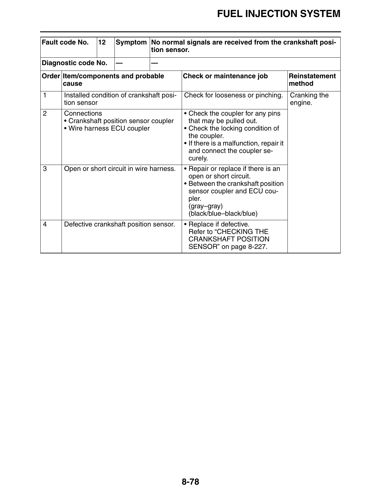
Fault code No. 12 Symptom No normal signals are received from the crankshaft posi-
tion sensor.
Diagnostic code No. — —
Order Item/components and probable Check or maintenance job Reinstatement
cause method
1 Installed condition of crankshaft posi- Check for looseness or pinching. Cranking the
tion sensor engine.
2 Connections • Check the coupler for any pins
• Crankshaft position sensor coupler that may be pulled out.
• Wire harness ECU coupler • Check the locking condition of
the coupler.
• If there is a malfunction, repair it
and connect the coupler se-
curely.
3 Open or short circuit in wire harness. • Repair or replace if there is an
open or short circuit.
• Between the crankshaft position
sensor coupler and ECU cou-
pler.
(gray–gray)
(black/blue–black/blue)
4 Defective crankshaft position sensor. • Replace if defective.
Refer to “CHECKING THE
CRANKSHAFT POSITION
SENSOR” on page 8-227.
8-78
FUEL INJECTION SYSTEM
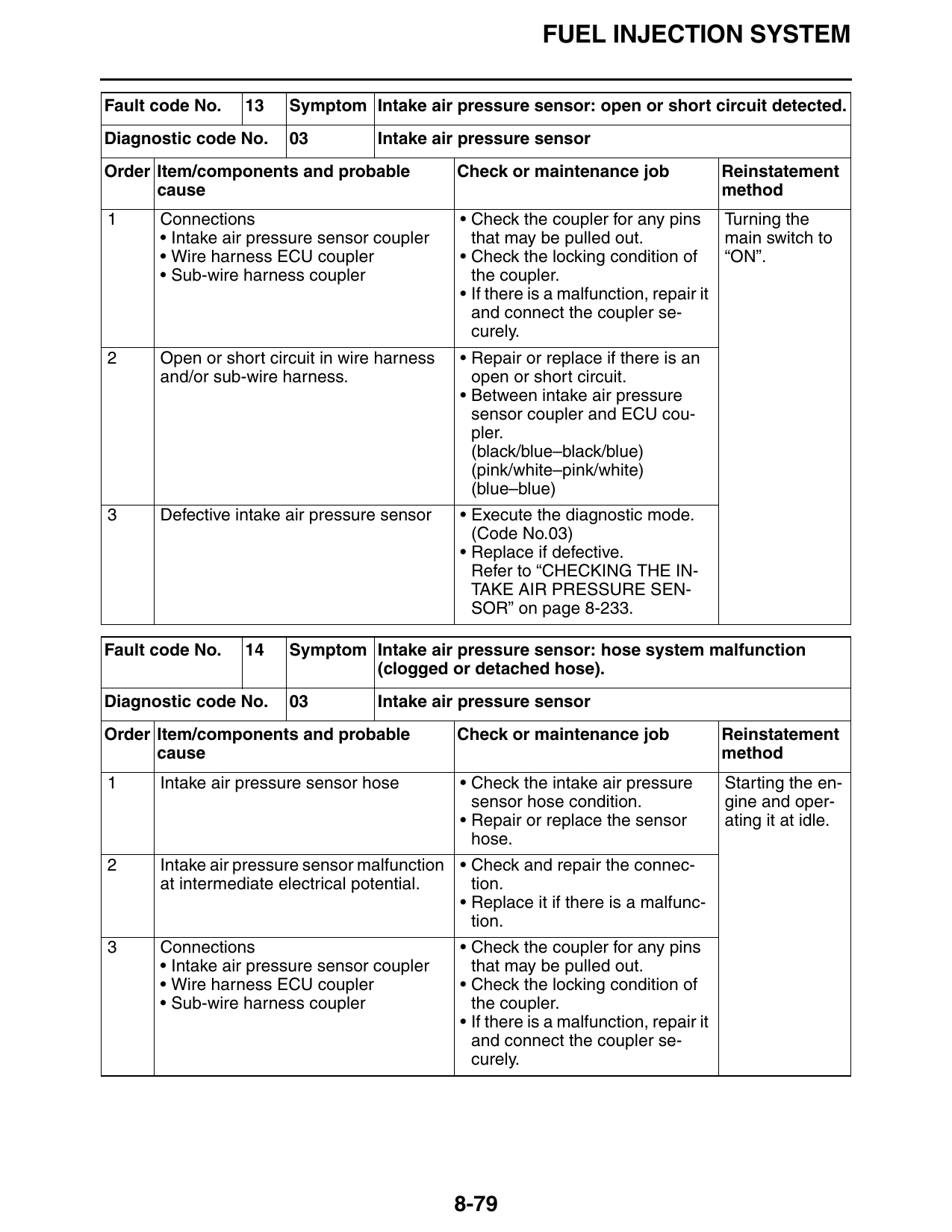
Fault code No. 13 Symptom Intake air pressure sensor: open or short circuit detected.
Diagnostic code No. 03 Intake air pressure sensor
Order Item/components and probable Check or maintenance job Reinstatement
cause method
1 Connections • Check the coupler for any pins Turning the
• Intake air pressure sensor coupler that may be pulled out. main switch to
• Wire harness ECU coupler • Check the locking condition of “ON”.
• Sub-wire harness coupler the coupler.
• If there is a malfunction, repair it
and connect the coupler se-
curely.
2 Open or short circuit in wire harness • Repair or replace if there is an
and/or sub-wire harness. open or short circuit.
• Between intake air pressure
sensor coupler and ECU cou-
pler.
(black/blue–black/blue)
(pink/white–pink/white)
(blue–blue)
3 Defective intake air pressure sensor • Execute the diagnostic mode.
(Code No.03)
• Replace if defective.
Refer to “CHECKING THE IN-
TAKE AIR PRESSURE SEN-
SOR” on page 8-233.
Fault code No. 14 Symptom Intake air pressure sensor: hose system malfunction
(clogged or detached hose).
Diagnostic code No. 03 Intake air pressure sensor
Order Item/components and probable Check or maintenance job Reinstatement
cause method
1 Intake air pressure sensor hose • Check the intake air pressure Starting the en-
sensor hose condition. gine and oper-
• Repair or replace the sensor ating it at idle.
hose.
2 Intake air pressure sensor malfunction • Check and repair the connec-
at intermediate electrical potential. tion.
• Replace it if there is a malfunc-
tion.
3 Connections • Check the coupler for any pins
• Intake air pressure sensor coupler that may be pulled out.
• Wire harness ECU coupler • Check the locking condition of
• Sub-wire harness coupler the coupler.
• If there is a malfunction, repair it
and connect the coupler se-
curely.
8-79
FUEL INJECTION SYSTEM
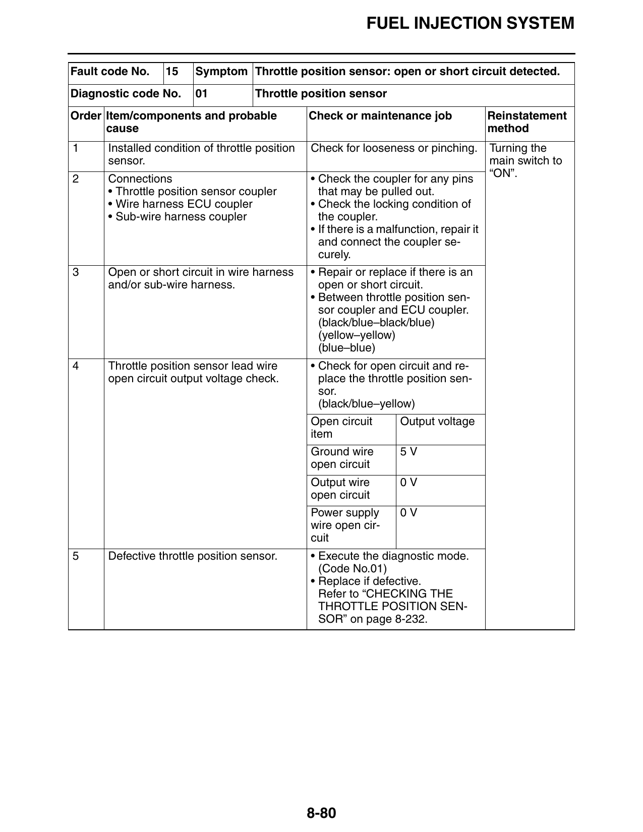
Fault code No. 15 Symptom Throttle position sensor: open or short circuit detected.
Diagnostic code No. 01 Throttle position sensor
Order Item/components and probable Check or maintenance job Reinstatement
cause method
1 Installed condition of throttle position Check for looseness or pinching. Turning the
sensor. main switch to
2 Connections • Check the coupler for any pins “ON”.
• Throttle position sensor coupler that may be pulled out.
• Wire harness ECU coupler • Check the locking condition of
• Sub-wire harness coupler the coupler.
• If there is a malfunction, repair it
and connect the coupler se-
curely.
3 Open or short circuit in wire harness • Repair or replace if there is an
and/or sub-wire harness. open or short circuit.
• Between throttle position sen-
sor coupler and ECU coupler.
(black/blue–black/blue)
(yellow–yellow)
(blue–blue)
4 Throttle position sensor lead wire • Check for open circuit and re-
open circuit output voltage check. place the throttle position sen-
sor.
(black/blue–yellow)
Open circuit Output voltage
item
Ground wire 5V
open circuit
Output wire 0V
open circuit
Power supply 0V
wire open cir-
cuit
5 Defective throttle position sensor. • Execute the diagnostic mode.
(Code No.01)
• Replace if defective.
Refer to “CHECKING THE
THROTTLE POSITION SEN-
SOR” on page 8-232.
8-80
FUEL INJECTION SYSTEM
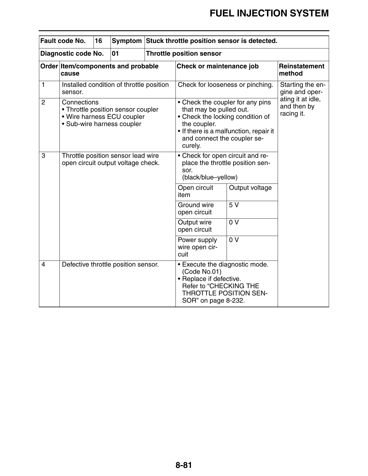
Fault code No. 16 Symptom Stuck throttle position sensor is detected.
Diagnostic code No. 01 Throttle position sensor
Order Item/components and probable Check or maintenance job Reinstatement
cause method
1 Installed condition of throttle position Check for looseness or pinching. Starting the en-
sensor. gine and oper-
2 Connections • Check the coupler for any pins ating it at idle,
• Throttle position sensor coupler that may be pulled out. and then by
• Wire harness ECU coupler • Check the locking condition of racing it.
• Sub-wire harness coupler the coupler.
• If there is a malfunction, repair it
and connect the coupler se-
curely.
3 Throttle position sensor lead wire • Check for open circuit and re-
open circuit output voltage check. place the throttle position sen-
sor.
(black/blue–yellow)
Open circuit Output voltage
item
Ground wire 5V
open circuit
Output wire 0V
open circuit
Power supply 0V
wire open cir-
cuit
4 Defective throttle position sensor. • Execute the diagnostic mode.
(Code No.01)
• Replace if defective.
Refer to “CHECKING THE
THROTTLE POSITION SEN-
SOR” on page 8-232.
8-81
FUEL INJECTION SYSTEM
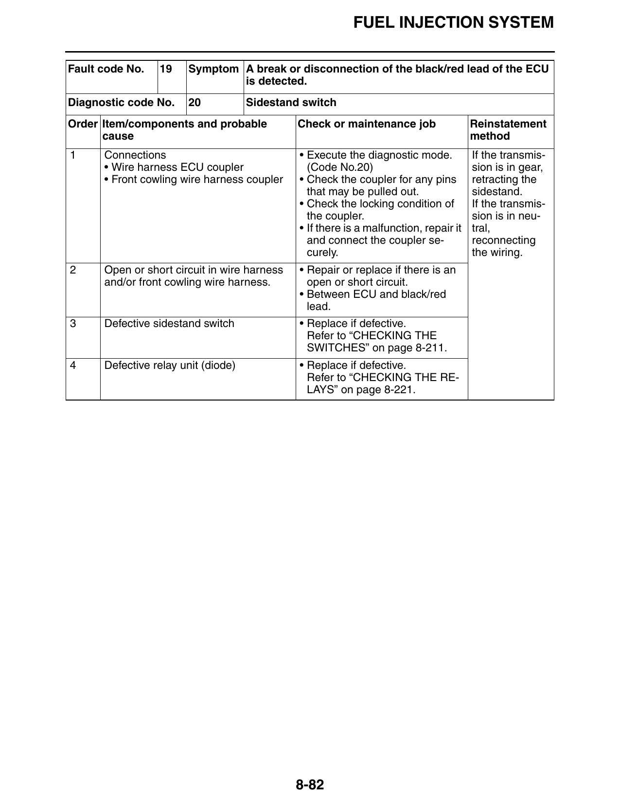
Fault code No. 19 Symptom A break or disconnection of the black/red lead of the ECU
is detected.
Diagnostic code No. 20 Sidestand switch
Order Item/components and probable Check or maintenance job Reinstatement
cause method
1 Connections • Execute the diagnostic mode. If the transmis-
• Wire harness ECU coupler (Code No.20) sion is in gear,
• Front cowling wire harness coupler • Check the coupler for any pins retracting the
that may be pulled out. sidestand.
• Check the locking condition of If the transmis-
the coupler. sion is in neu-
• If there is a malfunction, repair it tral,
and connect the coupler se- reconnecting
curely. the wiring.
2 Open or short circuit in wire harness • Repair or replace if there is an
and/or front cowling wire harness. open or short circuit.
• Between ECU and black/red
lead.
3 Defective sidestand switch • Replace if defective.
Refer to “CHECKING THE
SWITCHES” on page 8-211.
4 Defective relay unit (diode) • Replace if defective.
Refer to “CHECKING THE RE-
LAYS” on page 8-221.
8-82
FUEL INJECTION SYSTEM
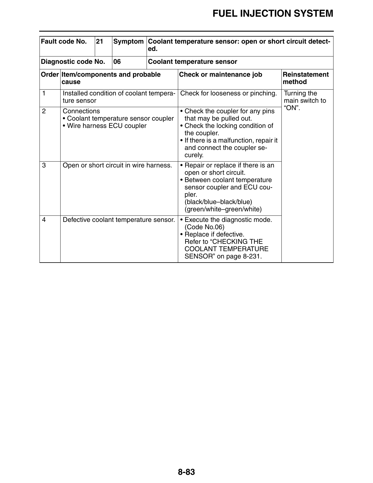
Fault code No. 21 Symptom Coolant temperature sensor: open or short circuit detect-
ed.
Diagnostic code No. 06 Coolant temperature sensor
Order Item/components and probable Check or maintenance job Reinstatement
cause method
1 Installed condition of coolant tempera- Check for looseness or pinching. Turning the
ture sensor main switch to
2 Connections • Check the coupler for any pins “ON”.
• Coolant temperature sensor coupler that may be pulled out.
• Wire harness ECU coupler • Check the locking condition of
the coupler.
• If there is a malfunction, repair it
and connect the coupler se-
curely.
3 Open or short circuit in wire harness. • Repair or replace if there is an
open or short circuit.
• Between coolant temperature
sensor coupler and ECU cou-
pler.
(black/blue–black/blue)
(green/white–green/white)
4 Defective coolant temperature sensor. • Execute the diagnostic mode.
(Code No.06)
• Replace if defective.
Refer to “CHECKING THE
COOLANT TEMPERATURE
SENSOR” on page 8-231.
8-83
FUEL INJECTION SYSTEM
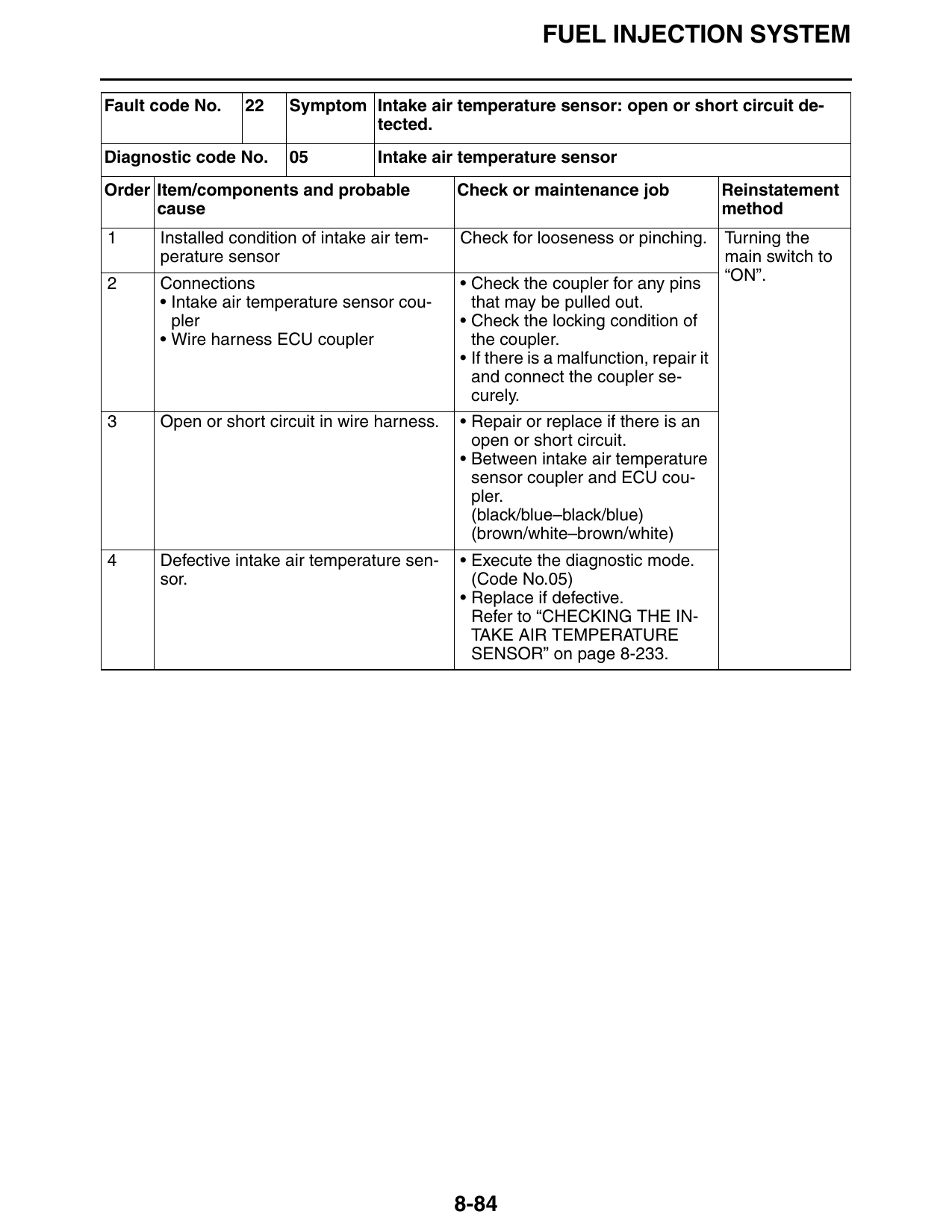
Fault code No. 22 Symptom Intake air temperature sensor: open or short circuit de-
tected.
Diagnostic code No. 05 Intake air temperature sensor
Order Item/components and probable Check or maintenance job Reinstatement
cause method
1 Installed condition of intake air tem- Check for looseness or pinching. Turning the
perature sensor main switch to
2 Connections • Check the coupler for any pins “ON”.
• Intake air temperature sensor cou- that may be pulled out.
pler • Check the locking condition of
• Wire harness ECU coupler the coupler.
• If there is a malfunction, repair it
and connect the coupler se-
curely.
3 Open or short circuit in wire harness. • Repair or replace if there is an
open or short circuit.
• Between intake air temperature
sensor coupler and ECU cou-
pler.
(black/blue–black/blue)
(brown/white–brown/white)
4 Defective intake air temperature sen- • Execute the diagnostic mode.
sor. (Code No.05)
• Replace if defective.
Refer to “CHECKING THE IN-
TAKE AIR TEMPERATURE
SENSOR” on page 8-233.
8-84
FUEL INJECTION SYSTEM
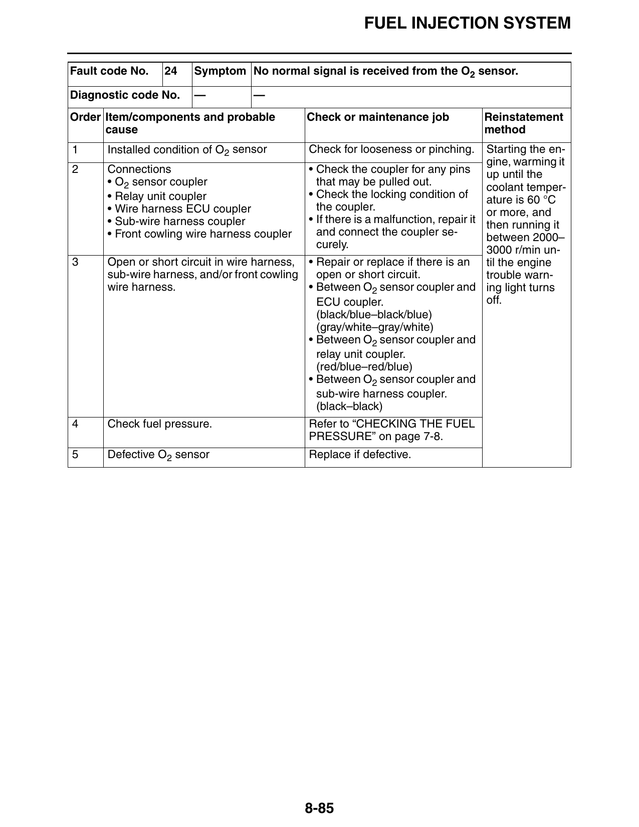
Fault code No. 24 Symptom No normal signal is received from the O2 sensor.
Diagnostic code No. — —
Order Item/components and probable Check or maintenance job Reinstatement
cause method
1 Installed condition of O2 sensor Check for looseness or pinching. Starting the en-
gine, warming it
2 Connections • Check the coupler for any pins up until the
• O2 sensor coupler that may be pulled out. coolant temper-
• Relay unit coupler • Check the locking condition of ature is 60 °C
• Wire harness ECU coupler the coupler. or more, and
• Sub-wire harness coupler • If there is a malfunction, repair it then running it
• Front cowling wire harness coupler and connect the coupler se- between 2000–
curely. 3000 r/min un-
3 Open or short circuit in wire harness, • Repair or replace if there is an til the engine
sub-wire harness, and/or front cowling open or short circuit. trouble warn-
wire harness. • Between O2 sensor coupler and ing light turns
ECU coupler. off.
(black/blue–black/blue)
(gray/white–gray/white)
• Between O2 sensor coupler and
relay unit coupler.
(red/blue–red/blue)
• Between O2 sensor coupler and
sub-wire harness coupler.
(black–black)
4 Check fuel pressure. Refer to “CHECKING THE FUEL
PRESSURE” on page 7-8.
5 Defective O2 sensor Replace if defective.
8-85
FUEL INJECTION SYSTEM
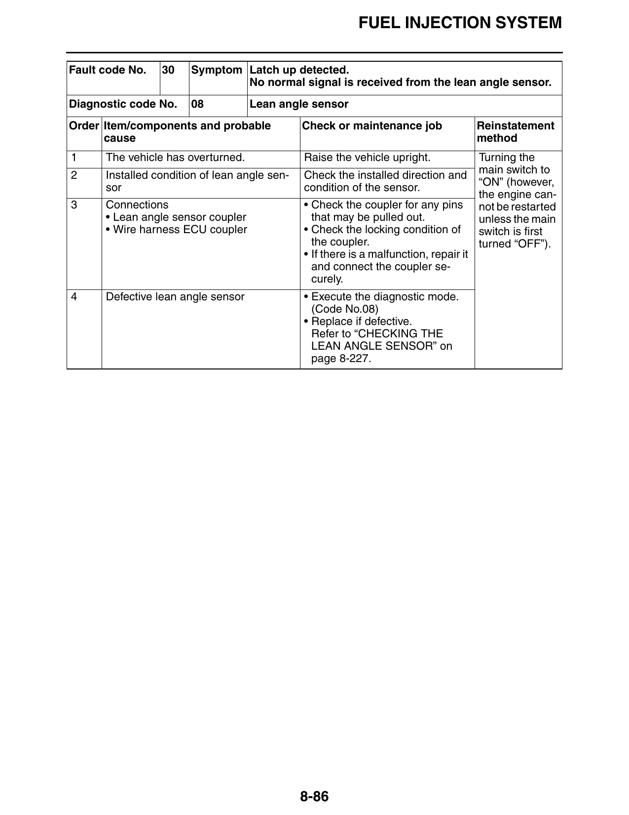
Fault code No. 30 Symptom Latch up detected.
No normal signal is received from the lean angle sensor.
Diagnostic code No. 08 Lean angle sensor
Order Item/components and probable Check or maintenance job Reinstatement
cause method
1 The vehicle has overturned. Raise the vehicle upright. Turning the
2 Installed condition of lean angle sen- Check the installed direction and main switch to
sor condition of the sensor. “ON” (however,
the engine can-
3 Connections • Check the coupler for any pins not be restarted
• Lean angle sensor coupler that may be pulled out. unless the main
• Wire harness ECU coupler • Check the locking condition of switch is first
the coupler. turned “OFF”).
• If there is a malfunction, repair it
and connect the coupler se-
curely.
4 Defective lean angle sensor • Execute the diagnostic mode.
(Code No.08)
• Replace if defective.
Refer to “CHECKING THE
LEAN ANGLE SENSOR” on
page 8-227.
8-86
FUEL INJECTION SYSTEM
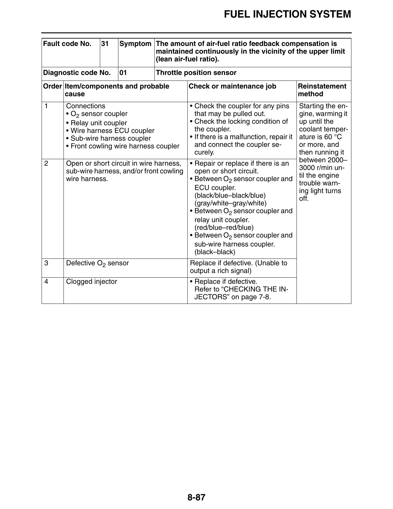
Fault code No. 31 Symptom The amount of air-fuel ratio feedback compensation is
maintained continuously in the vicinity of the upper limit
(lean air-fuel ratio).
Diagnostic code No. 01 Throttle position sensor
Order Item/components and probable Check or maintenance job Reinstatement
cause method
1 Connections • Check the coupler for any pins Starting the en-
• O2 sensor coupler that may be pulled out. gine, warming it
• Relay unit coupler • Check the locking condition of up until the
• Wire harness ECU coupler the coupler. coolant temper-
• Sub-wire harness coupler • If there is a malfunction, repair it
ature is 60 °C
• Front cowling wire harness coupler and connect the coupler se- or more, and
curely. then running it
2 Open or short circuit in wire harness, • Repair or replace if there is an between 2000–
sub-wire harness, and/or front cowling open or short circuit. 3000 r/min un-
wire harness. • Between O2 sensor coupler and til the engine
trouble warn-
ECU coupler. ing light turns
(black/blue–black/blue) off.
(gray/white–gray/white)
• Between O2 sensor coupler and
relay unit coupler.
(red/blue–red/blue)
• Between O2 sensor coupler and
sub-wire harness coupler.
(black–black)
3 Defective O2 sensor Replace if defective. (Unable to
output a rich signal)
4 Clogged injector • Replace if defective.
Refer to “CHECKING THE IN-
JECTORS” on page 7-8.
8-87
FUEL INJECTION SYSTEM
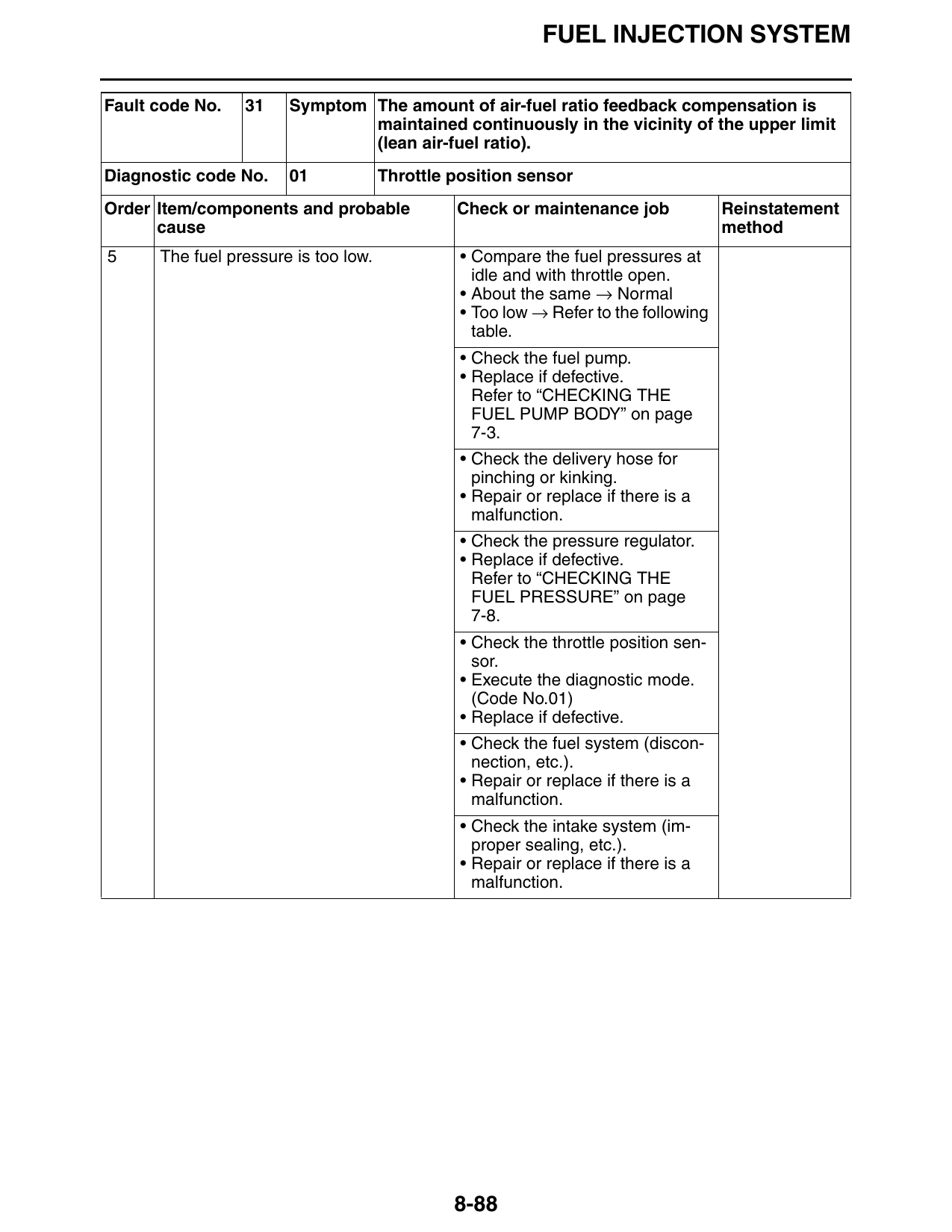
Fault code No. 31 Symptom The amount of air-fuel ratio feedback compensation is
maintained continuously in the vicinity of the upper limit
(lean air-fuel ratio).
Diagnostic code No. 01 Throttle position sensor
Order Item/components and probable Check or maintenance job Reinstatement
cause method
5 The fuel pressure is too low. • Compare the fuel pressures at
idle and with throttle open.
• About the same → Normal
• Too low → Refer to the following
table.
• Check the fuel pump.
• Replace if defective.
Refer to “CHECKING THE
FUEL PUMP BODY” on page
7-3.
• Check the delivery hose for
pinching or kinking.
• Repair or replace if there is a
malfunction.
• Check the pressure regulator.
• Replace if defective.
Refer to “CHECKING THE
FUEL PRESSURE” on page
7-8.
• Check the throttle position sen-
sor.
• Execute the diagnostic mode.
(Code No.01)
• Replace if defective.
• Check the fuel system (discon-
nection, etc.).
• Repair or replace if there is a
malfunction.
• Check the intake system (im-
proper sealing, etc.).
• Repair or replace if there is a
malfunction.
8-88
FUEL INJECTION SYSTEM
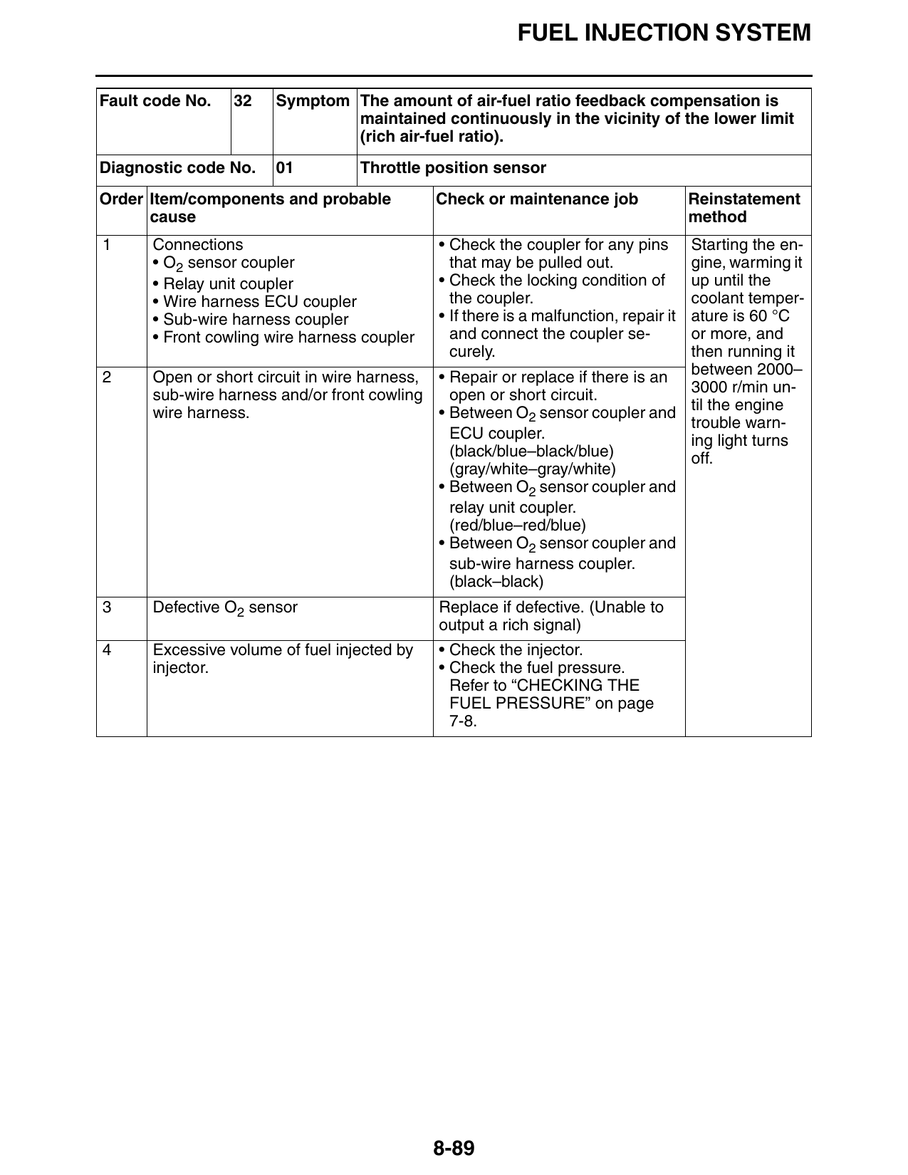
Fault code No. 32 Symptom The amount of air-fuel ratio feedback compensation is
maintained continuously in the vicinity of the lower limit
(rich air-fuel ratio).
Diagnostic code No. 01 Throttle position sensor
Order Item/components and probable Check or maintenance job Reinstatement
cause method
1 Connections • Check the coupler for any pins Starting the en-
• O2 sensor coupler that may be pulled out. gine, warming it
• Relay unit coupler • Check the locking condition of up until the
• Wire harness ECU coupler the coupler. coolant temper-
• Sub-wire harness coupler • If there is a malfunction, repair it
ature is 60 °C
• Front cowling wire harness coupler and connect the coupler se- or more, and
curely. then running it
2 Open or short circuit in wire harness, • Repair or replace if there is an between 2000–
sub-wire harness and/or front cowling open or short circuit. 3000 r/min un-
wire harness. • Between O2 sensor coupler and til the engine
trouble warn-
ECU coupler. ing light turns
(black/blue–black/blue) off.
(gray/white–gray/white)
• Between O2 sensor coupler and
relay unit coupler.
(red/blue–red/blue)
• Between O2 sensor coupler and
sub-wire harness coupler.
(black–black)
3 Defective O2 sensor Replace if defective. (Unable to
output a rich signal)
4 Excessive volume of fuel injected by • Check the injector.
injector. • Check the fuel pressure.
Refer to “CHECKING THE
FUEL PRESSURE” on page
7-8.
8-89
FUEL INJECTION SYSTEM
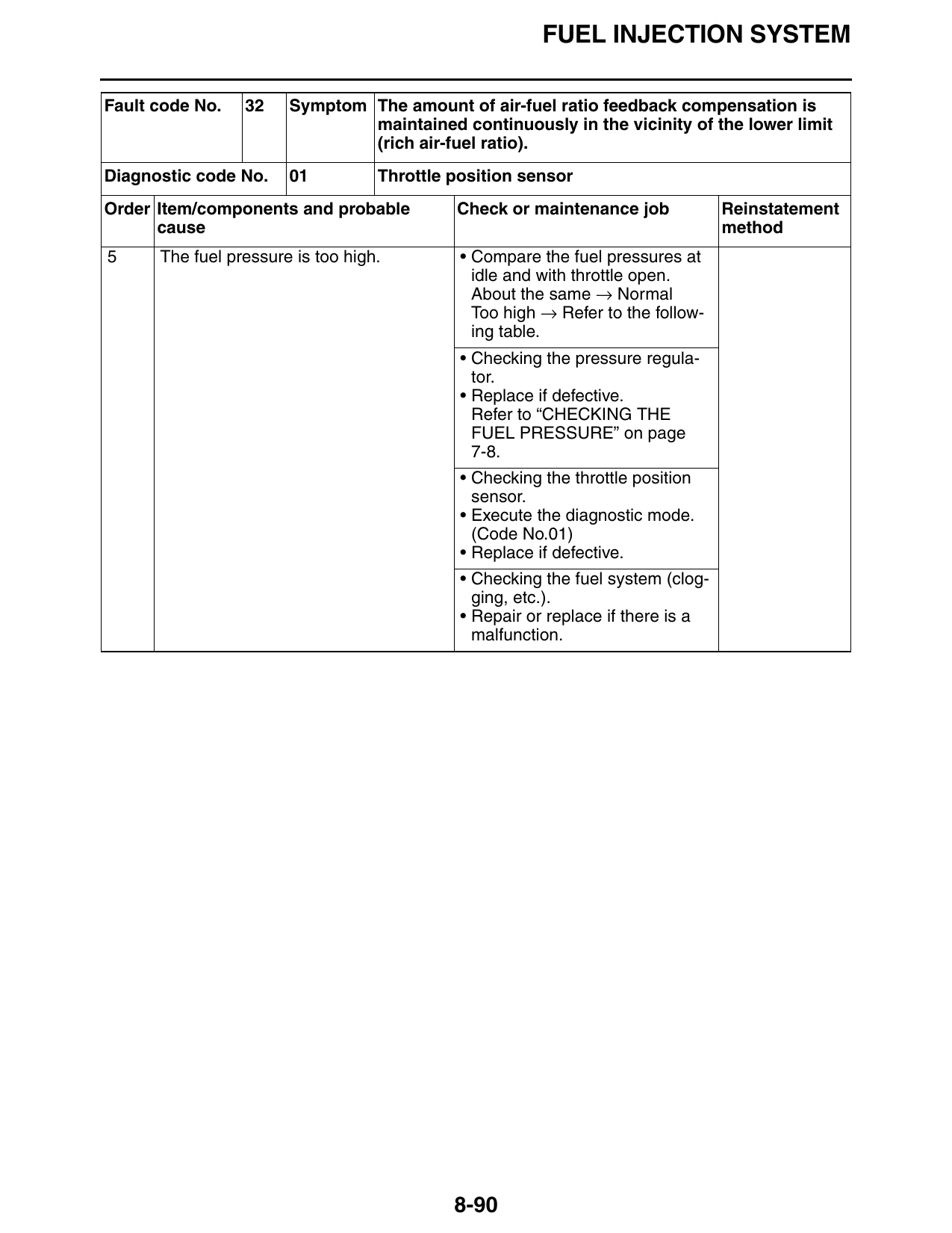
Fault code No. 32 Symptom The amount of air-fuel ratio feedback compensation is
maintained continuously in the vicinity of the lower limit
(rich air-fuel ratio).
Diagnostic code No. 01 Throttle position sensor
Order Item/components and probable Check or maintenance job Reinstatement
cause method
5 The fuel pressure is too high. • Compare the fuel pressures at
idle and with throttle open.
About the same → Normal
Too high → Refer to the follow-
ing table.
• Checking the pressure regula-
tor.
• Replace if defective.
Refer to “CHECKING THE
FUEL PRESSURE” on page
7-8.
• Checking the throttle position
sensor.
• Execute the diagnostic mode.
(Code No.01)
• Replace if defective.
• Checking the fuel system (clog-
ging, etc.).
• Repair or replace if there is a
malfunction.
8-90
FUEL INJECTION SYSTEM
Fault code No. 33 Symptom Malfunction detected in the primary wire of the cylinders-
#1/#4 ignition coil.
Diagnostic code No. 30 Cylinders-#1/#4 ignition coil
Order Item/components and probable Check or maintenance job Reinstatement
cause method
1 Connections • Check the coupler for any pins Starting the en-
• Cylinders-#1/#4 ignition coil connec- that may be pulled out. gine and oper-
tor (primary coil side) • Check the locking condition of ating it at idle.
• Wire harness ECU coupler the coupler.
• Front cowling wire harness coupler • If there is a malfunction, repair it
and connect the coupler se-
curely.
2 Open or short circuit in wire harness • Repair or replace if there is an
and/or front cowling wire harness. open or short circuit.
• Between cylinders-#1/#4 igni-
tion coil connector and ECU
coupler.
(orange–orange)
• Between cylinders-#1/#4 igni-
tion coil connector and right
handlebar switch coupler.
(red/black–red/black)
3 Defective cylinders-#1/#4 ignition coil • Execute the diagnostic mode.
(Code No.30)
• Test the primary and secondary
coils for continuity.
• Replace if defective.
Refer to “CHECKING THE IG-
NITION COILS” on page 8-226.
8-91
FUEL INJECTION SYSTEM
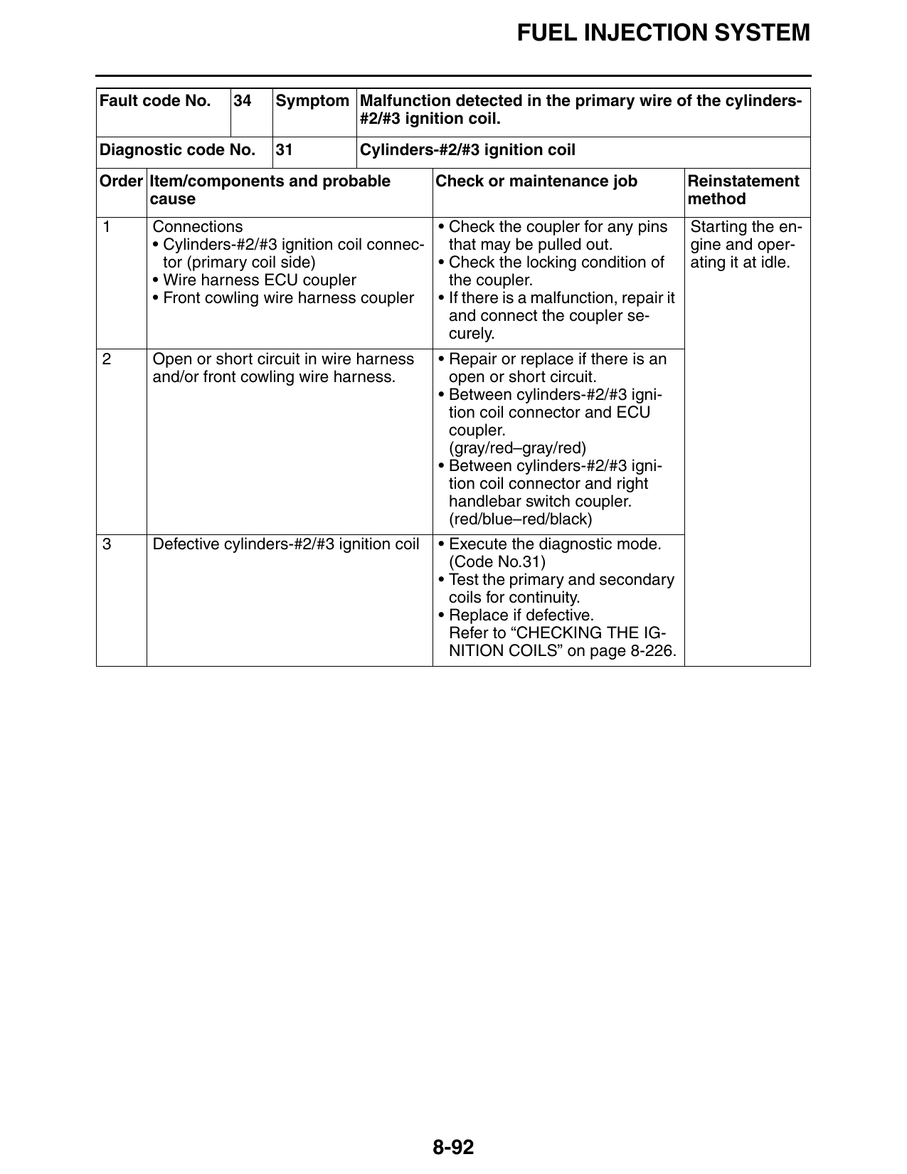
Fault code No. 34 Symptom Malfunction detected in the primary wire of the cylinders-
#2/#3 ignition coil.
Diagnostic code No. 31 Cylinders-#2/#3 ignition coil
Order Item/components and probable Check or maintenance job Reinstatement
cause method
1 Connections • Check the coupler for any pins Starting the en-
• Cylinders-#2/#3 ignition coil connec- that may be pulled out. gine and oper-
tor (primary coil side) • Check the locking condition of ating it at idle.
• Wire harness ECU coupler the coupler.
• Front cowling wire harness coupler • If there is a malfunction, repair it
and connect the coupler se-
curely.
2 Open or short circuit in wire harness • Repair or replace if there is an
and/or front cowling wire harness. open or short circuit.
• Between cylinders-#2/#3 igni-
tion coil connector and ECU
coupler.
(gray/red–gray/red)
• Between cylinders-#2/#3 igni-
tion coil connector and right
handlebar switch coupler.
(red/blue–red/black)
3 Defective cylinders-#2/#3 ignition coil • Execute the diagnostic mode.
(Code No.31)
• Test the primary and secondary
coils for continuity.
• Replace if defective.
Refer to “CHECKING THE IG-
NITION COILS” on page 8-226.
8-92
FUEL INJECTION SYSTEM
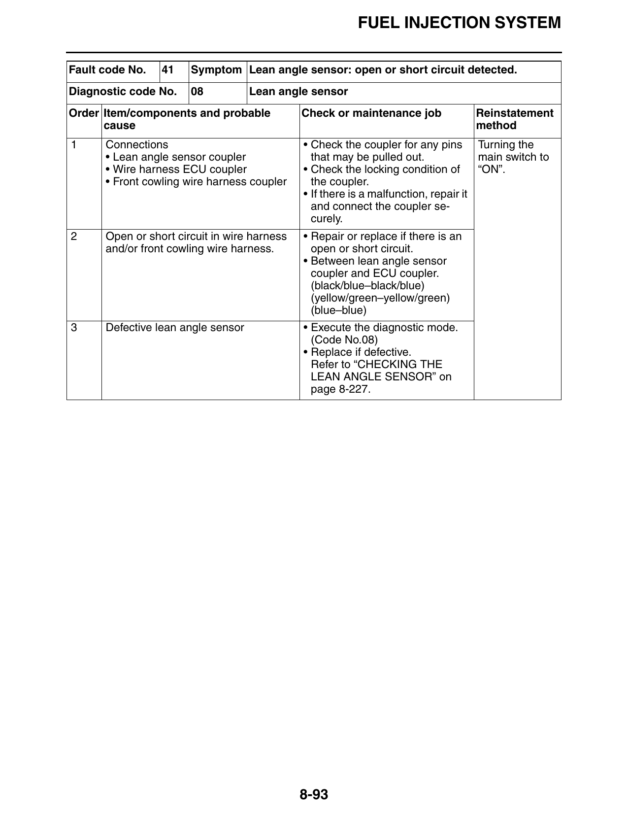
Fault code No. 41 Symptom Lean angle sensor: open or short circuit detected.
Diagnostic code No. 08 Lean angle sensor
Order Item/components and probable Check or maintenance job Reinstatement
cause method
1 Connections • Check the coupler for any pins Turning the
• Lean angle sensor coupler that may be pulled out. main switch to
• Wire harness ECU coupler • Check the locking condition of “ON”.
• Front cowling wire harness coupler the coupler.
• If there is a malfunction, repair it
and connect the coupler se-
curely.
2 Open or short circuit in wire harness • Repair or replace if there is an
and/or front cowling wire harness. open or short circuit.
• Between lean angle sensor
coupler and ECU coupler.
(black/blue–black/blue)
(yellow/green–yellow/green)
(blue–blue)
3 Defective lean angle sensor • Execute the diagnostic mode.
(Code No.08)
• Replace if defective.
Refer to “CHECKING THE
LEAN ANGLE SENSOR” on
page 8-227.
8-93
FUEL INJECTION SYSTEM
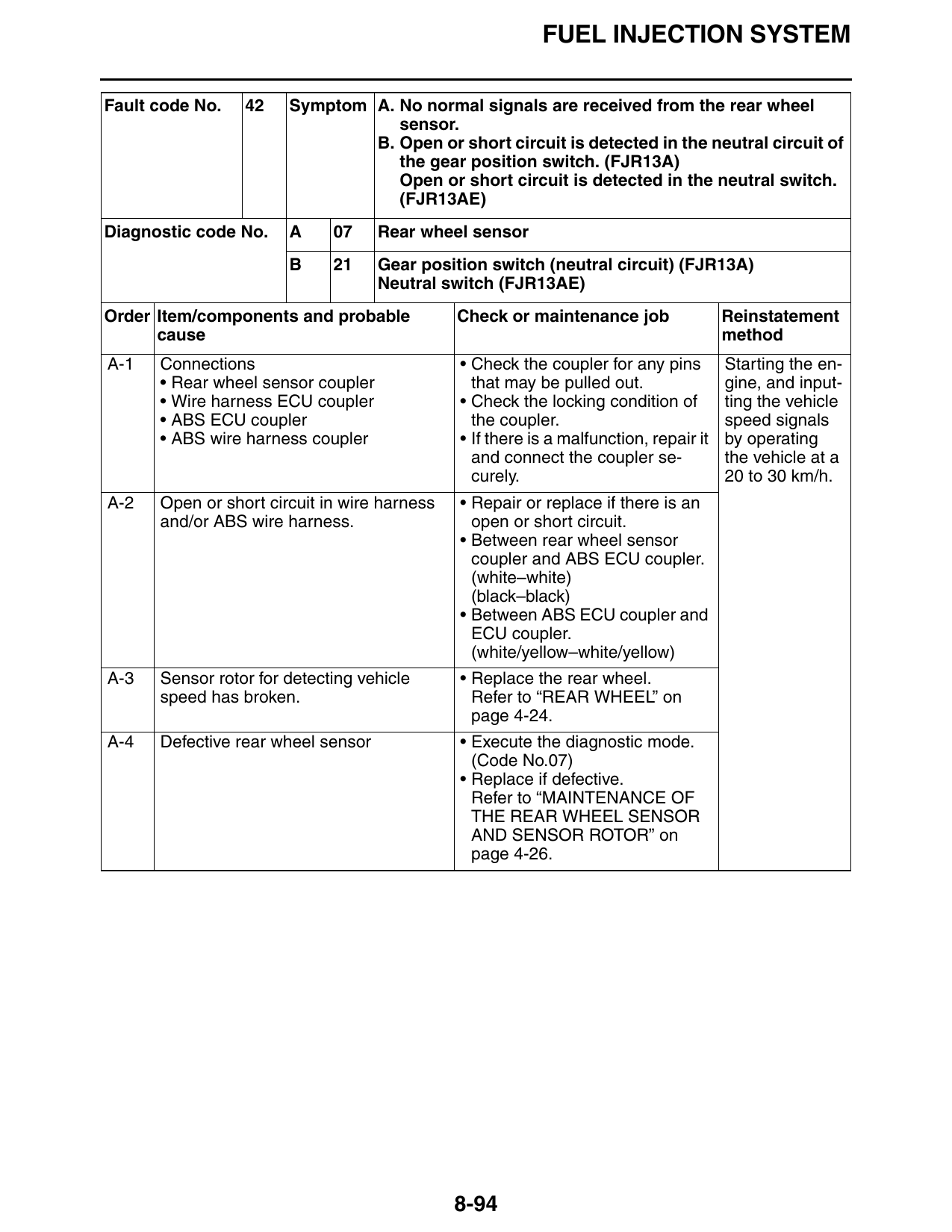
Fault code No. 42 Symptom A. No normal signals are received from the rear wheel
sensor.
B. Open or short circuit is detected in the neutral circuit of
the gear position switch. (FJR13A)
Open or short circuit is detected in the neutral switch.
(FJR13AE)
Diagnostic code No. A 07 Rear wheel sensor
B 21 Gear position switch (neutral circuit) (FJR13A)
Neutral switch (FJR13AE)
Order Item/components and probable Check or maintenance job Reinstatement
cause method
A-1 Connections • Check the coupler for any pins Starting the en-
• Rear wheel sensor coupler that may be pulled out. gine, and input-
• Wire harness ECU coupler • Check the locking condition of ting the vehicle
• ABS ECU coupler the coupler. speed signals
• ABS wire harness coupler • If there is a malfunction, repair it by operating
and connect the coupler se- the vehicle at a
curely. 20 to 30 km/h.
A-2 Open or short circuit in wire harness • Repair or replace if there is an
and/or ABS wire harness. open or short circuit.
• Between rear wheel sensor
coupler and ABS ECU coupler.
(white–white)
(black–black)
• Between ABS ECU coupler and
ECU coupler.
(white/yellow–white/yellow)
A-3 Sensor rotor for detecting vehicle • Replace the rear wheel.
speed has broken. Refer to “REAR WHEEL” on
page 4-24.
A-4 Defective rear wheel sensor • Execute the diagnostic mode.
(Code No.07)
• Replace if defective.
Refer to “MAINTENANCE OF
THE REAR WHEEL SENSOR
AND SENSOR ROTOR” on
page 4-26.
8-94
FUEL INJECTION SYSTEM
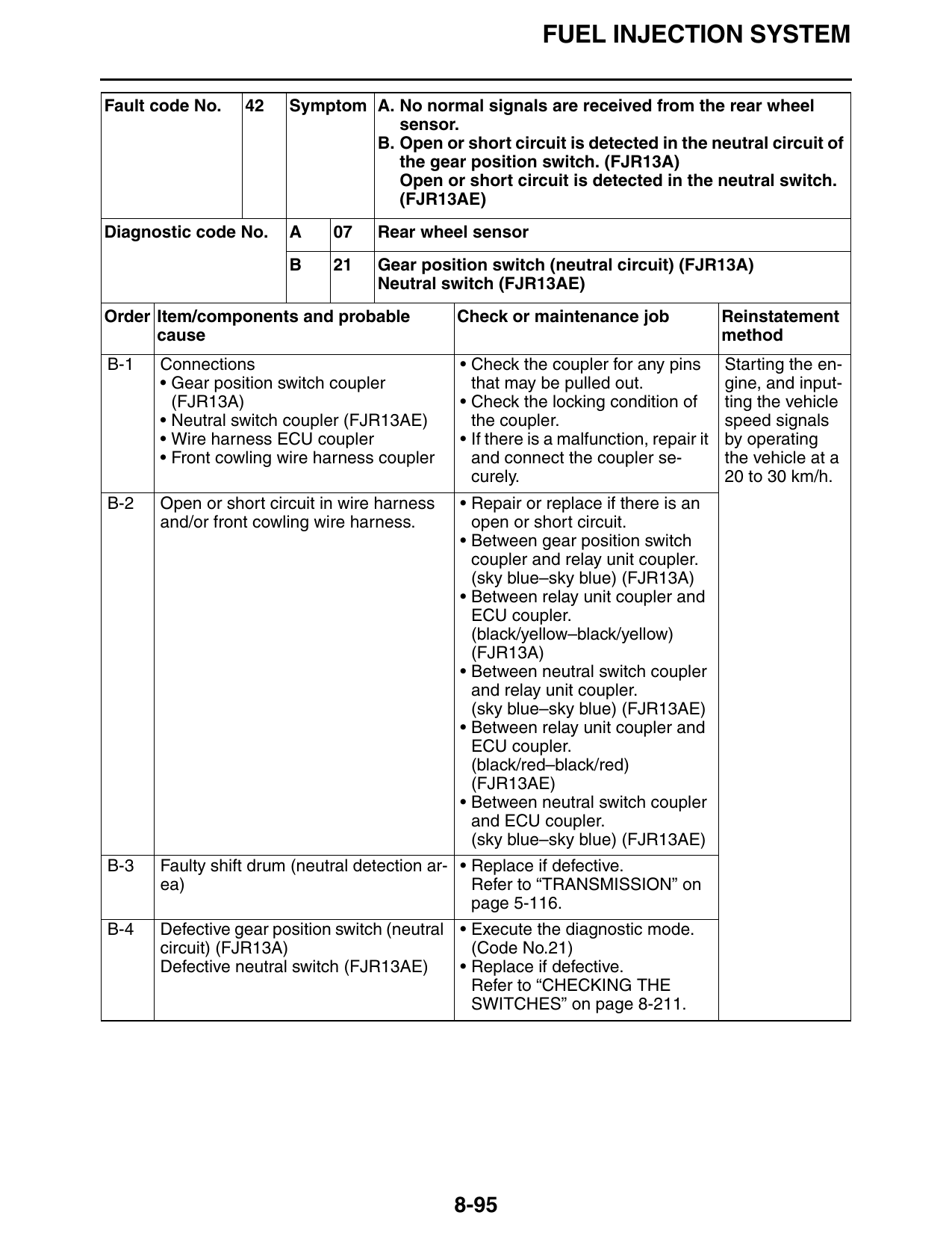
Fault code No. 42 Symptom A. No normal signals are received from the rear wheel
sensor.
B. Open or short circuit is detected in the neutral circuit of
the gear position switch. (FJR13A)
Open or short circuit is detected in the neutral switch.
(FJR13AE)
Diagnostic code No. A 07 Rear wheel sensor
B 21 Gear position switch (neutral circuit) (FJR13A)
Neutral switch (FJR13AE)
Order Item/components and probable Check or maintenance job Reinstatement
cause method
B-1 Connections • Check the coupler for any pins Starting the en-
• Gear position switch coupler that may be pulled out. gine, and input-
(FJR13A) • Check the locking condition of ting the vehicle
• Neutral switch coupler (FJR13AE) the coupler. speed signals
• Wire harness ECU coupler • If there is a malfunction, repair it by operating
• Front cowling wire harness coupler and connect the coupler se- the vehicle at a
curely. 20 to 30 km/h.
B-2 Open or short circuit in wire harness • Repair or replace if there is an
and/or front cowling wire harness. open or short circuit.
• Between gear position switch
coupler and relay unit coupler.
(sky blue–sky blue) (FJR13A)
• Between relay unit coupler and
ECU coupler.
(black/yellow–black/yellow)
(FJR13A)
• Between neutral switch coupler
and relay unit coupler.
(sky blue–sky blue) (FJR13AE)
• Between relay unit coupler and
ECU coupler.
(black/red–black/red)
(FJR13AE)
• Between neutral switch coupler
and ECU coupler.
(sky blue–sky blue) (FJR13AE)
B-3 Faulty shift drum (neutral detection ar- • Replace if defective.
ea) Refer to “TRANSMISSION” on
page 5-116.
B-4 Defective gear position switch (neutral • Execute the diagnostic mode.
circuit) (FJR13A) (Code No.21)
Defective neutral switch (FJR13AE) • Replace if defective.
Refer to “CHECKING THE
SWITCHES” on page 8-211.
8-95
FUEL INJECTION SYSTEM
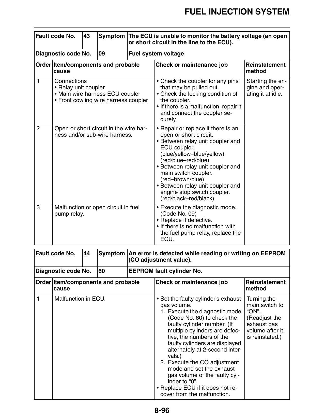
Fault code No. 43 Symptom The ECU is unable to monitor the battery voltage (an open
or short circuit in the line to the ECU).
Diagnostic code No. 09 Fuel system voltage
Order Item/components and probable Check or maintenance job Reinstatement
cause method
1 Connections • Check the coupler for any pins Starting the en-
• Relay unit coupler that may be pulled out. gine and oper-
• Main wire harness ECU coupler • Check the locking condition of ating it at idle.
• Front cowling wire harness coupler the coupler.
• If there is a malfunction, repair it
and connect the coupler se-
curely.
2 Open or short circuit in the wire har- • Repair or replace if there is an
ness and/or sub-wire harness. open or short circuit.
• Between relay unit coupler and
ECU coupler.
(blue/yellow–blue/yellow)
(red/blue–red/blue)
• Between relay unit coupler and
main switch coupler.
(red–brown/blue)
• Between relay unit coupler and
engine stop switch coupler.
(red/black–red/black)
3 Malfunction or open circuit in fuel • Execute the diagnostic mode.
pump relay. (Code No. 09)
• Replace if defective.
• If there is no malfunction with
the fuel pump relay, replace the
ECU.
Fault code No. 44 Symptom An error is detected while reading or writing on EEPROM
(CO adjustment value).
Diagnostic code No. 60 EEPROM fault cylinder No.
Order Item/components and probable Check or maintenance job Reinstatement
cause method
1 Malfunction in ECU. • Set the faulty cylinder’s exhaust Turning the
gas volume. main switch to
1. Execute the diagnostic mode “ON”.
(Code No. 60) to check the (Readjust the
faulty cylinder number. (If exhaust gas
multiple cylinders are defec- volume after it
tive, the numbers of the is reinstated.)
faulty cylinders are displayed
alternately at 2-second inter-
vals.)
2. Execute the CO adjustment
mode and set the exhaust
gas volume of the faulty cyl-
inder to “0”.
• Replace ECU if it does not re-
cover from the malfunction.
8-96
FUEL INJECTION SYSTEM
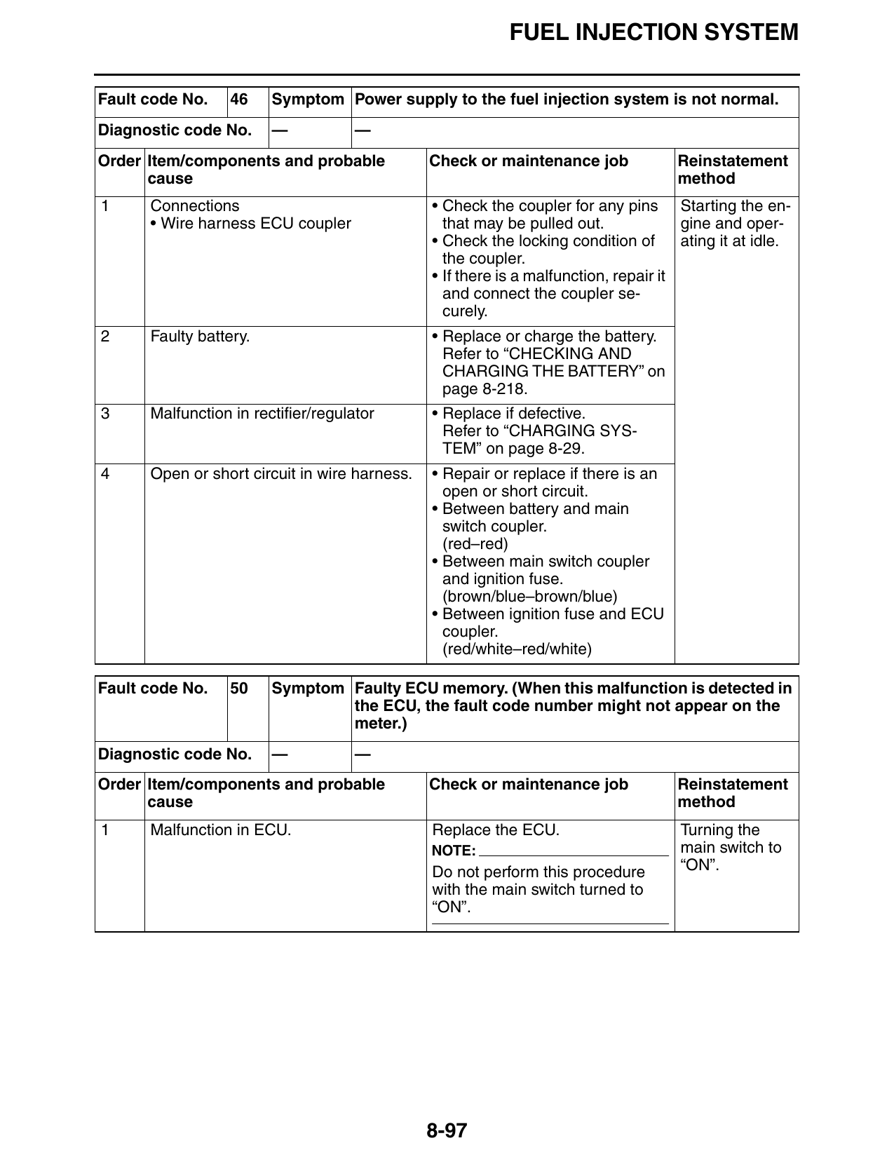
Fault code No. 46 Symptom Power supply to the fuel injection system is not normal.
Diagnostic code No. — —
Order Item/components and probable Check or maintenance job Reinstatement
cause method
1 Connections • Check the coupler for any pins Starting the en-
• Wire harness ECU coupler that may be pulled out. gine and oper-
• Check the locking condition of ating it at idle.
the coupler.
• If there is a malfunction, repair it
and connect the coupler se-
curely.
2 Faulty battery. • Replace or charge the battery.
Refer to “CHECKING AND
CHARGING THE BATTERY” on
page 8-218.
3 Malfunction in rectifier/regulator • Replace if defective.
Refer to “CHARGING SYS-
TEM” on page 8-29.
4 Open or short circuit in wire harness. • Repair or replace if there is an
open or short circuit.
• Between battery and main
switch coupler.
(red–red)
• Between main switch coupler
and ignition fuse.
(brown/blue–brown/blue)
• Between ignition fuse and ECU
coupler.
(red/white–red/white)
Fault code No. 50 Symptom Faulty ECU memory. (When this malfunction is detected in
the ECU, the fault code number might not appear on the
meter.)
Diagnostic code No. — —
Order Item/components and probable Check or maintenance job Reinstatement
cause method
1 Malfunction in ECU. Replace the ECU. Turning the
NOTE: main switch to
Do not perform this procedure “ON”.
with the main switch turned to
“ON”.
8-97
FUEL INJECTION SYSTEM
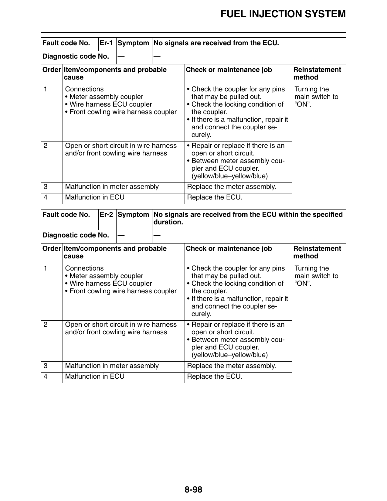
Fault code No. Er-1 Symptom No signals are received from the ECU.
Diagnostic code No. — —
Order Item/components and probable Check or maintenance job Reinstatement
cause method
1 Connections • Check the coupler for any pins Turning the
• Meter assembly coupler that may be pulled out. main switch to
• Wire harness ECU coupler • Check the locking condition of “ON”.
• Front cowling wire harness coupler the coupler.
• If there is a malfunction, repair it
and connect the coupler se-
curely.
2 Open or short circuit in wire harness • Repair or replace if there is an
and/or front cowling wire harness open or short circuit.
• Between meter assembly cou-
pler and ECU coupler.
(yellow/blue–yellow/blue)
3 Malfunction in meter assembly Replace the meter assembly.
4 Malfunction in ECU Replace the ECU.
Fault code No. Er-2 Symptom No signals are received from the ECU within the specified
duration.
Diagnostic code No. — —
Order Item/components and probable Check or maintenance job Reinstatement
cause method
1 Connections • Check the coupler for any pins Turning the
• Meter assembly coupler that may be pulled out. main switch to
• Wire harness ECU coupler • Check the locking condition of “ON”.
• Front cowling wire harness coupler the coupler.
• If there is a malfunction, repair it
and connect the coupler se-
curely.
2 Open or short circuit in wire harness • Repair or replace if there is an
and/or front cowling wire harness open or short circuit.
• Between meter assembly cou-
pler and ECU coupler.
(yellow/blue–yellow/blue)
3 Malfunction in meter assembly Replace the meter assembly.
4 Malfunction in ECU Replace the ECU.
8-98
FUEL INJECTION SYSTEM
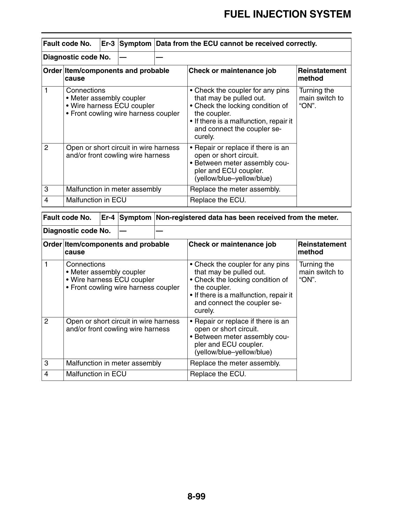
Fault code No. Er-3 Symptom Data from the ECU cannot be received correctly.
Diagnostic code No. — —
Order Item/components and probable Check or maintenance job Reinstatement
cause method
1 Connections • Check the coupler for any pins Turning the
• Meter assembly coupler that may be pulled out. main switch to
• Wire harness ECU coupler • Check the locking condition of “ON”.
• Front cowling wire harness coupler the coupler.
• If there is a malfunction, repair it
and connect the coupler se-
curely.
2 Open or short circuit in wire harness • Repair or replace if there is an
and/or front cowling wire harness open or short circuit.
• Between meter assembly cou-
pler and ECU coupler.
(yellow/blue–yellow/blue)
3 Malfunction in meter assembly Replace the meter assembly.
4 Malfunction in ECU Replace the ECU.
Fault code No. Er-4 Symptom Non-registered data has been received from the meter.
Diagnostic code No. — —
Order Item/components and probable Check or maintenance job Reinstatement
cause method
1 Connections • Check the coupler for any pins Turning the
• Meter assembly coupler that may be pulled out. main switch to
• Wire harness ECU coupler • Check the locking condition of “ON”.
• Front cowling wire harness coupler the coupler.
• If there is a malfunction, repair it
and connect the coupler se-
curely.
2 Open or short circuit in wire harness • Repair or replace if there is an
and/or front cowling wire harness open or short circuit.
• Between meter assembly cou-
pler and ECU coupler.
(yellow/blue–yellow/blue)
3 Malfunction in meter assembly Replace the meter assembly.
4 Malfunction in ECU Replace the ECU.
8-99
FUEL INJECTION SYSTEM
8-100