Diagnostic Mode
Fragment manuala — str. 646–649
📋 Tekst do skopiowania / wyszukiwania
YCC-S (Yamaha Chip Controlled-Shift) SYSTEM (FJR13AE only)
5. Erase the malfunction history in the diagnos-
tic mode. Refer to “Diagnostic code table (Di-
agnostic code No. Sh_ _62)”.
NOTE:
Turning the main switch to “OFF” will not erase
the malfunction history.
ET3P66064
DIAGNOSTIC MODE
Setting the diagnostic mode
1. Turn the main switch to “OFF”.
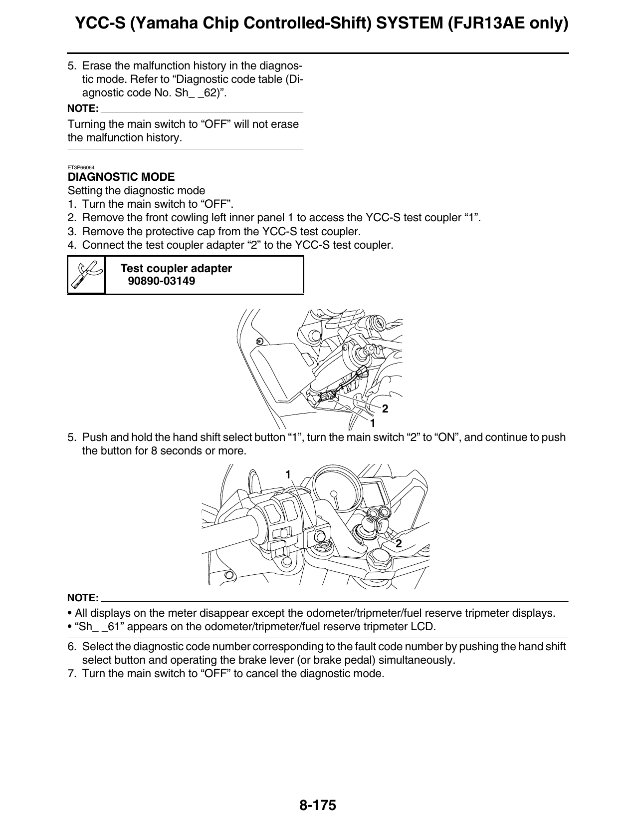
2. Remove the front cowling left inner panel 1 to access the YCC-S test coupler “1”.
3. Remove the protective cap from the YCC-S test coupler.
4. Connect the test coupler adapter “2” to the YCC-S test coupler.
Test coupler adapter
90890-03149
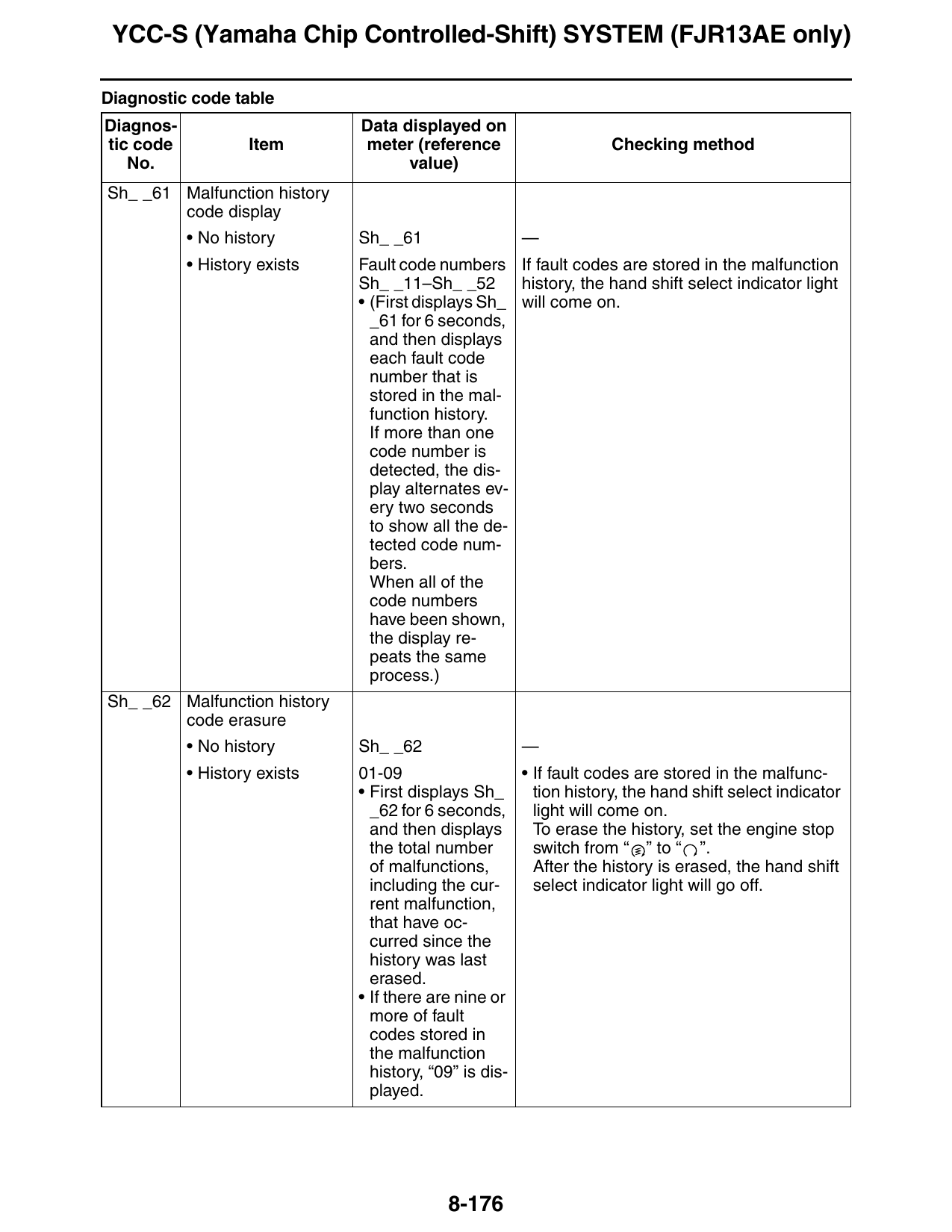
5. Push and hold the hand shift select button “1”, turn the main switch “2” to “ON”, and continue to push
the button for 8 seconds or more.
NOTE:
• All displays on the meter disappear except the odometer/tripmeter/fuel reserve tripmeter displays.
• “Sh_ _61” appears on the odometer/tripmeter/fuel reserve tripmeter LCD.
6. Select the diagnostic code number corresponding to the fault code number by pushing the hand shift
select button and operating the brake lever (or brake pedal) simultaneously.
7. Turn the main switch to “OFF” to cancel the diagnostic mode.
8-175
YCC-S (Yamaha Chip Controlled-Shift) SYSTEM (FJR13AE only)
Diagnostic code table
Diagnos- Data displayed on
tic code Item meter (reference Checking method
No. value)
Sh_ _61 Malfunction history
code display
• No history Sh_ _61 —
• History exists Fault code numbers If fault codes are stored in the malfunction
Sh_ _11–Sh_ _52 history, the hand shift select indicator light
• (First displays Sh_ will come on.
_61 for 6 seconds,
and then displays
each fault code
number that is
stored in the mal-
function history.
If more than one
code number is
detected, the dis-
play alternates ev-
ery two seconds
to show all the de-
tected code num-
bers.
When all of the
code numbers
have been shown,
the display re-
peats the same
process.)
Sh_ _62 Malfunction history
code erasure
• No history Sh_ _62 —
• History exists 01-09 • If fault codes are stored in the malfunc-
• First displays Sh_ tion history, the hand shift select indicator
_62 for 6 seconds, light will come on.
and then displays To erase the history, set the engine stop
the total number switch from “ ” to “ ”.
of malfunctions, After the history is erased, the hand shift
including the cur- select indicator light will go off.
rent malfunction,
that have oc-
curred since the
history was last
erased.
• If there are nine or
more of fault
codes stored in
the malfunction
history, “09” is dis-
played.
8-176
YCC-S (Yamaha Chip Controlled-Shift) SYSTEM (FJR13AE only)
Diagnos- Data displayed on
tic code Item meter (reference Checking method
No. value)
Sh_ _63 Clutch actuation op- Sh_ _63 The clutch actuator can be operated in this
eration mode.
NOTE: 1. The hand shift select indicator light
The checking meth- comes on when the clutch is engaged.
od for the diagnostic 2. Set the engine stop switch to “ ” and
code (Sh_ _63) can- push the hand shift select button simul-
not be performed taneously. The clutch will disengage
when any of the fol- and the hand shift select indicator light
lowing fault codes will go off.
are detected. 3. Set the engine stop switch to “ ” and
Sh_ _11, Sh_ _12, push the hand shift select button simul-
Sh_ _13, Sh_ _15, taneously. The clutch will engage and
Sh_ 16, Sh_ _17, the hand shift select indicator light will
Sh_ _25, Sh_ _26, come on.
Sh_ _36, Sh_ _37, 4. If the clutch actuator sensor is malfunc-
and Sh_ _44 tioning, the hand shift select indicator
light will flash.
Sh_ _64 Shift actuator opera- Sh_ _64 The shift actuator can be operated in this
tion mode.
NOTE: 1. Make sure that the transmission is in
The checking meth- neutral.
od for the diagnostic 2. Set the engine stop switch to “ ” and
code (Sh_ _64) can- operate the hand shift lever switch (shift
not be performed up) simultaneously. The MCU (motor
when any of the fol- control unit) operates the shift actuator
lowing fault codes once.
are detected. The shift actuator is operated once
Sh_ _11, Sh_ _12, each time two switches are operated.
Sh_ _14, Sh_ _15, 3. The MCU (motor control unit) detects
Sh_ 16, Sh_ _18, the signal from the shift actuator sensor.
Sh_ _19, Sh_ _25, If the signal received after upshifting is
Sh_ _37, and Sh_ correct, the hand shift select indicator
_51 light will come on.
If the signal received after upshifting in
incorrect, the hand shift select indicator
light will flash.
4. Set the engine stop switch to “ ” and
operate the hand shift lever switch (shift
down) simultaneously. The MCU (motor
control unit) operates the shift actuator
once.
The shift actuator is operated once
each time two switches are operated.
5. The MCU (motor control unit) detects
the signal from the shift actuator sensor.
If the signal received after downshifting
is correct, the hand shift select indicator
light will come on.
If the signal received after downshifting
is incorrect, the hand shift select indica-
tor light will flash.
8-177
YCC-S (Yamaha Chip Controlled-Shift) SYSTEM (FJR13AE only)
Diagnos- Data displayed on
tic code Item meter (reference Checking method
No. value)
Sh_ _65 Gear position setting Sh_ _65 The gear position can be set in this mode.
1. Make sure that the transmission is in
neutral.
2. Push the start switch.
If the gear position sensor output signal
is correct for the neutral position, the
hand shift select indicator light will
come on for 0.5 second.
3. Shift the transmission into 1st gear us-
ing the hand shift lever switch (shift up),
and then rotate the rear wheel at least
1/2 turn by hand to ensure that the dog
completely engages the 1st gear.
4. Push the start switch.
If the gear position sensor output signal
is correct for the 1st gear position, the
hand shift select indicator light will
come on for 0.5 second.
5. Repeat steps 3 and 4 for each gear up
to the 5th gear and make sure that the
hand shift select indicator light comes
on for 0.5 second each time the start
switch is pushed.
6. Shift the transmission into 4th gear us-
ing the hand shift lever switch (shift
down), and then rotate the rear wheel at
least 1/2 turn by hand to ensure that the
dog completely engages the 4th gear.
7. Push the start switch.
If the gear position sensor output signal
is correct for the 4th gear position, the
hand shift select indicator light will
come on for 0.5 second.
8. Repeat steps 6 and 7 for each gear
down to the 1st gear and make sure
that the hand shift select indicator light
comes on for 0.5 second each time the
start switch is pushed.
9. Shift the transmission into neutral.
10.After the above procedure is complet-
ed, all of the gear position data is tem-
porarily stored and ready to be written
on EEPROM.
11.Operate the brake lever or brake pedal
to write the data on EEPROM.
If all of the data has been written suc-
cessfully on EEPROM, the hand shift
select indicator light will come on for 2
seconds.
If the data is not written successfully,
the hand shift select indicator light will
flash.
8-178