Troubleshooting Details
Fragment manuala — str. 650–673
📋 Tekst do skopiowania / wyszukiwania
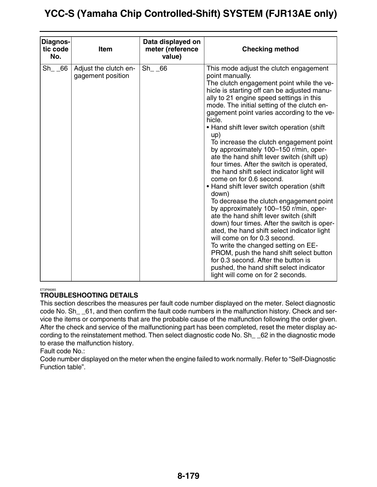
YCC-S (Yamaha Chip Controlled-Shift) SYSTEM (FJR13AE only)
Diagnos- Data displayed on
tic code Item meter (reference Checking method
No. value)
Sh_ _66 Adjust the clutch en- Sh_ _66 This mode adjust the clutch engagement
gagement position point manually.
The clutch engagement point while the ve-
hicle is starting off can be adjusted manu-
ally to 21 engine speed settings in this
mode. The initial setting of the clutch en-
gagement point varies according to the ve-
hicle.
• Hand shift lever switch operation (shift
up)
To increase the clutch engagement point
by approximately 100–150 r/min, oper-
ate the hand shift lever switch (shift up)
four times. After the switch is operated,
the hand shift select indicator light will
come on for 0.6 second.
• Hand shift lever switch operation (shift
down)
To decrease the clutch engagement point
by approximately 100–150 r/min, oper-
ate the hand shift lever switch (shift
down) four times. After the switch is oper-
ated, the hand shift select indicator light
will come on for 0.3 second.
To write the changed setting on EE-
PROM, push the hand shift select button
for 0.3 second. After the button is
pushed, the hand shift select indicator
light will come on for 2 seconds.
ET3P66065
TROUBLESHOOTING DETAILS
This section describes the measures per fault code number displayed on the meter. Select diagnostic
code No. Sh_ _61, and then confirm the fault code numbers in the malfunction history. Check and ser-
vice the items or components that are the probable cause of the malfunction following the order given.
After the check and service of the malfunctioning part has been completed, reset the meter display ac-
cording to the reinstatement method. Then select diagnostic code No. Sh_ _62 in the diagnostic mode
to erase the malfunction history.
Fault code No.:
Code number displayed on the meter when the engine failed to work normally. Refer to “Self-Diagnostic
Function table”.
8-179
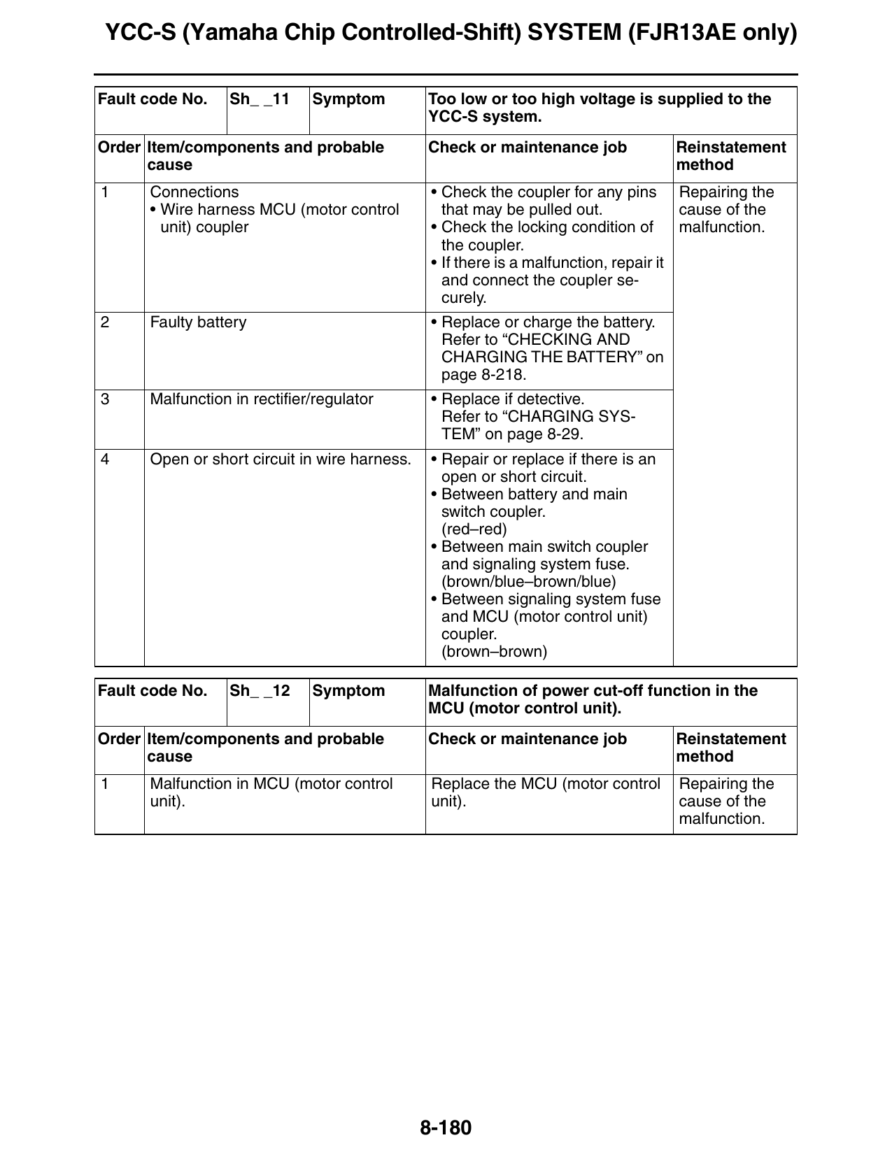
YCC-S (Yamaha Chip Controlled-Shift) SYSTEM (FJR13AE only)
Fault code No. Sh_ _11 Symptom Too low or too high voltage is supplied to the
YCC-S system.
Order Item/components and probable Check or maintenance job Reinstatement
cause method
1 Connections • Check the coupler for any pins Repairing the
• Wire harness MCU (motor control that may be pulled out. cause of the
unit) coupler • Check the locking condition of malfunction.
the coupler.
• If there is a malfunction, repair it
and connect the coupler se-
curely.
2 Faulty battery • Replace or charge the battery.
Refer to “CHECKING AND
CHARGING THE BATTERY” on
page 8-218.
3 Malfunction in rectifier/regulator • Replace if detective.
Refer to “CHARGING SYS-
TEM” on page 8-29.
4 Open or short circuit in wire harness. • Repair or replace if there is an
open or short circuit.
• Between battery and main
switch coupler.
(red–red)
• Between main switch coupler
and signaling system fuse.
(brown/blue–brown/blue)
• Between signaling system fuse
and MCU (motor control unit)
coupler.
(brown–brown)
Fault code No. Sh_ _12 Symptom Malfunction of power cut-off function in the
MCU (motor control unit).
Order Item/components and probable Check or maintenance job Reinstatement
cause method
1 Malfunction in MCU (motor control Replace the MCU (motor control Repairing the
unit). unit). cause of the
malfunction.
8-180
YCC-S (Yamaha Chip Controlled-Shift) SYSTEM (FJR13AE only)
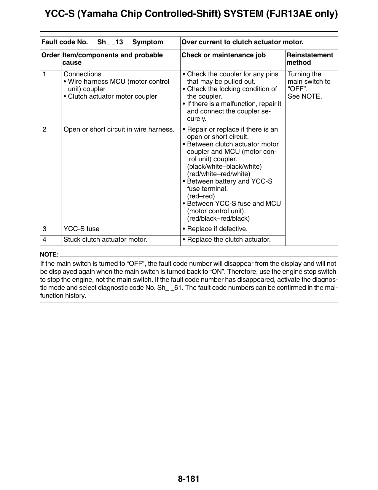
Fault code No. Sh_ _13 Symptom Over current to clutch actuator motor.
Order Item/components and probable Check or maintenance job Reinstatement
cause method
1 Connections • Check the coupler for any pins Turning the
• Wire harness MCU (motor control that may be pulled out. main switch to
unit) coupler • Check the locking condition of “OFF”.
• Clutch actuator motor coupler the coupler. See NOTE.
• If there is a malfunction, repair it
and connect the coupler se-
curely.
2 Open or short circuit in wire harness. • Repair or replace if there is an
open or short circuit.
• Between clutch actuator motor
coupler and MCU (motor con-
trol unit) coupler.
(black/white–black/white)
(red/white–red/white)
• Between battery and YCC-S
fuse terminal.
(red–red)
• Between YCC-S fuse and MCU
(motor control unit).
(red/black–red/black)
3 YCC-S fuse • Replace if defective.
4 Stuck clutch actuator motor. • Replace the clutch actuator.
NOTE:
If the main switch is turned to “OFF”, the fault code number will disappear from the display and will not
be displayed again when the main switch is turned back to “ON”. Therefore, use the engine stop switch
to stop the engine, not the main switch. If the fault code number has disappeared, activate the diagnos-
tic mode and select diagnostic code No. Sh_ _61. The fault code numbers can be confirmed in the mal-
function history.
8-181
YCC-S (Yamaha Chip Controlled-Shift) SYSTEM (FJR13AE only)
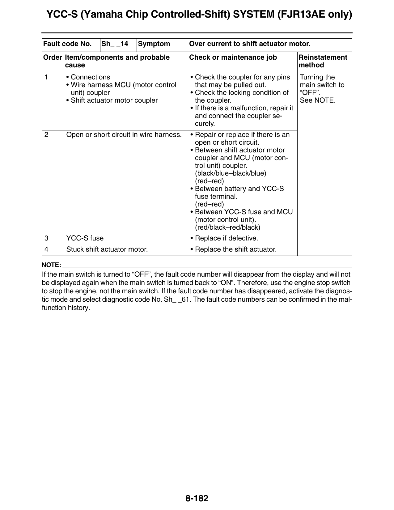
Fault code No. Sh_ _14 Symptom Over current to shift actuator motor.
Order Item/components and probable Check or maintenance job Reinstatement
cause method
1 • Connections • Check the coupler for any pins Turning the
• Wire harness MCU (motor control that may be pulled out. main switch to
unit) coupler • Check the locking condition of “OFF”.
• Shift actuator motor coupler the coupler. See NOTE.
• If there is a malfunction, repair it
and connect the coupler se-
curely.
2 Open or short circuit in wire harness. • Repair or replace if there is an
open or short circuit.
• Between shift actuator motor
coupler and MCU (motor con-
trol unit) coupler.
(black/blue–black/blue)
(red–red)
• Between battery and YCC-S
fuse terminal.
(red–red)
• Between YCC-S fuse and MCU
(motor control unit).
(red/black–red/black)
3 YCC-S fuse • Replace if defective.
4 Stuck shift actuator motor. • Replace the shift actuator.
NOTE:
If the main switch is turned to “OFF”, the fault code number will disappear from the display and will not
be displayed again when the main switch is turned back to “ON”. Therefore, use the engine stop switch
to stop the engine, not the main switch. If the fault code number has disappeared, activate the diagnos-
tic mode and select diagnostic code No. Sh_ _61. The fault code numbers can be confirmed in the mal-
function history.
8-182
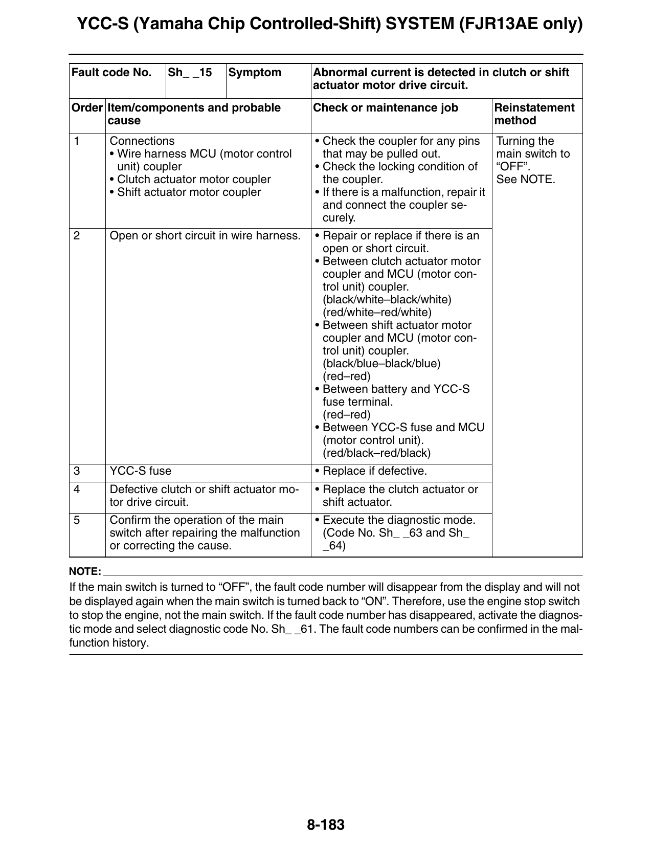
YCC-S (Yamaha Chip Controlled-Shift) SYSTEM (FJR13AE only)
Fault code No. Sh_ _15 Symptom Abnormal current is detected in clutch or shift
actuator motor drive circuit.
Order Item/components and probable Check or maintenance job Reinstatement
cause method
1 Connections • Check the coupler for any pins Turning the
• Wire harness MCU (motor control that may be pulled out. main switch to
unit) coupler • Check the locking condition of “OFF”.
• Clutch actuator motor coupler the coupler. See NOTE.
• Shift actuator motor coupler • If there is a malfunction, repair it
and connect the coupler se-
curely.
2 Open or short circuit in wire harness. • Repair or replace if there is an
open or short circuit.
• Between clutch actuator motor
coupler and MCU (motor con-
trol unit) coupler.
(black/white–black/white)
(red/white–red/white)
• Between shift actuator motor
coupler and MCU (motor con-
trol unit) coupler.
(black/blue–black/blue)
(red–red)
• Between battery and YCC-S
fuse terminal.
(red–red)
• Between YCC-S fuse and MCU
(motor control unit).
(red/black–red/black)
3 YCC-S fuse • Replace if defective.
4 Defective clutch or shift actuator mo- • Replace the clutch actuator or
tor drive circuit. shift actuator.
5 Confirm the operation of the main • Execute the diagnostic mode.
switch after repairing the malfunction (Code No. Sh_ _63 and Sh_
or correcting the cause. _64)
NOTE:
If the main switch is turned to “OFF”, the fault code number will disappear from the display and will not
be displayed again when the main switch is turned back to “ON”. Therefore, use the engine stop switch
to stop the engine, not the main switch. If the fault code number has disappeared, activate the diagnos-
tic mode and select diagnostic code No. Sh_ _61. The fault code numbers can be confirmed in the mal-
function history.
8-183
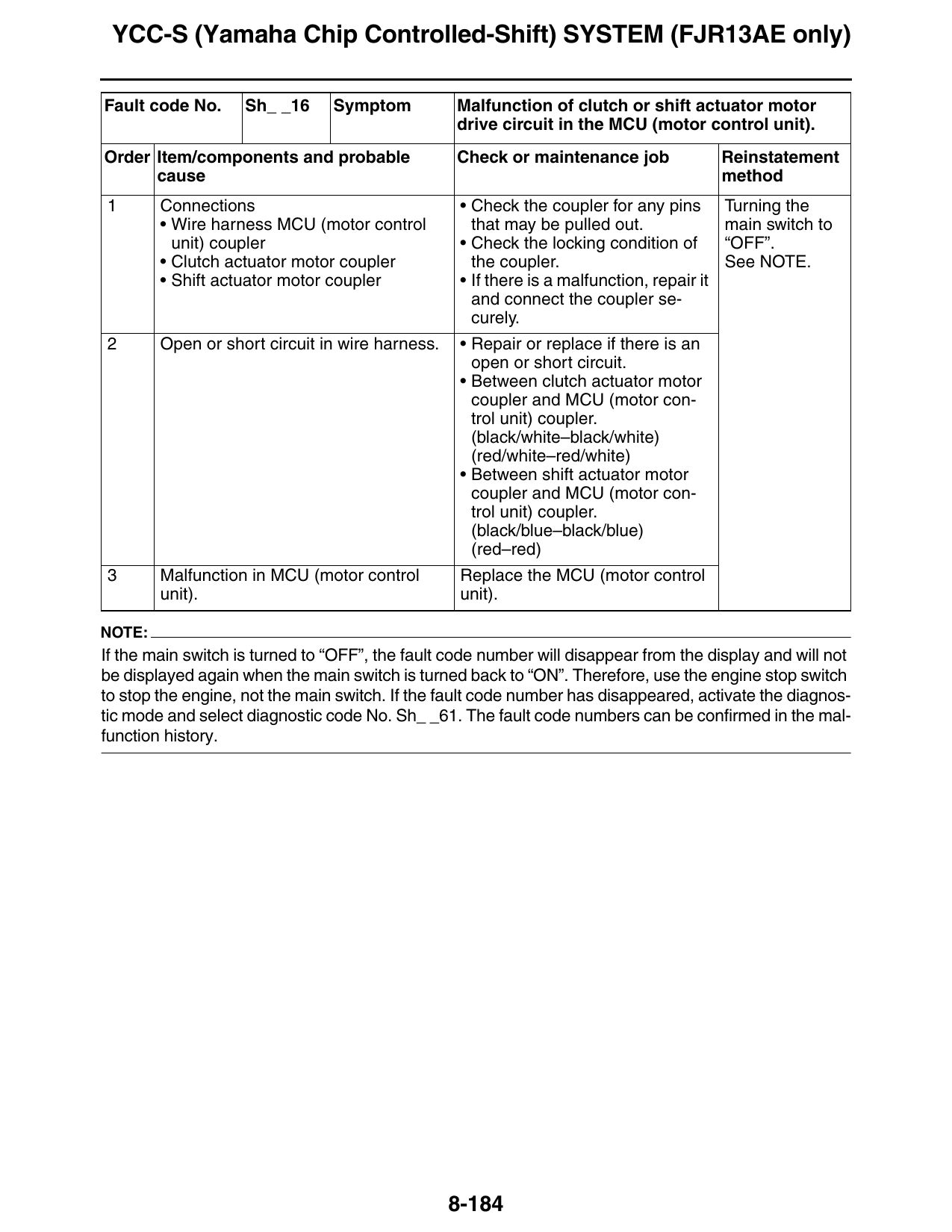
YCC-S (Yamaha Chip Controlled-Shift) SYSTEM (FJR13AE only)
Fault code No. Sh_ _16 Symptom Malfunction of clutch or shift actuator motor
drive circuit in the MCU (motor control unit).
Order Item/components and probable Check or maintenance job Reinstatement
cause method
1 Connections • Check the coupler for any pins Turning the
• Wire harness MCU (motor control that may be pulled out. main switch to
unit) coupler • Check the locking condition of “OFF”.
• Clutch actuator motor coupler the coupler. See NOTE.
• Shift actuator motor coupler • If there is a malfunction, repair it
and connect the coupler se-
curely.
2 Open or short circuit in wire harness. • Repair or replace if there is an
open or short circuit.
• Between clutch actuator motor
coupler and MCU (motor con-
trol unit) coupler.
(black/white–black/white)
(red/white–red/white)
• Between shift actuator motor
coupler and MCU (motor con-
trol unit) coupler.
(black/blue–black/blue)
(red–red)
3 Malfunction in MCU (motor control Replace the MCU (motor control
unit). unit).
NOTE:
If the main switch is turned to “OFF”, the fault code number will disappear from the display and will not
be displayed again when the main switch is turned back to “ON”. Therefore, use the engine stop switch
to stop the engine, not the main switch. If the fault code number has disappeared, activate the diagnos-
tic mode and select diagnostic code No. Sh_ _61. The fault code numbers can be confirmed in the mal-
function history.
8-184
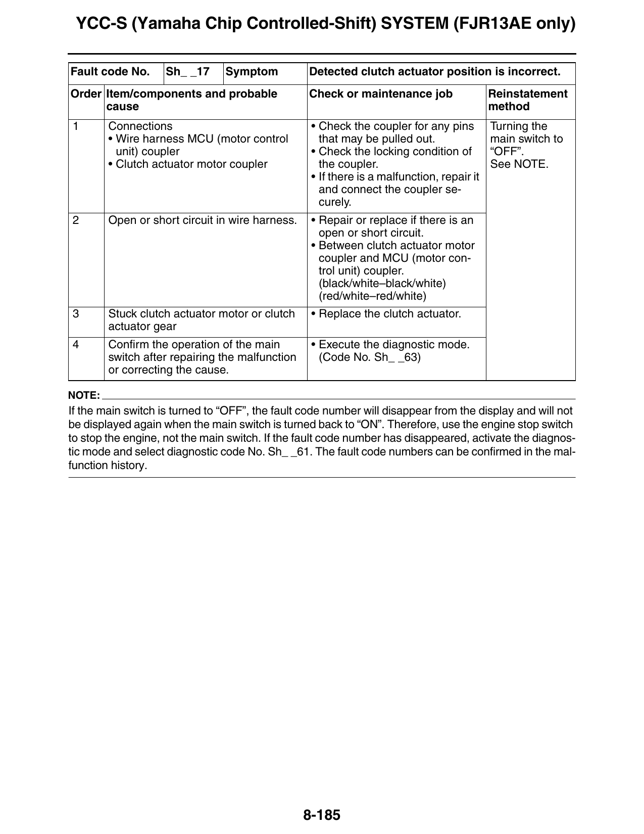
YCC-S (Yamaha Chip Controlled-Shift) SYSTEM (FJR13AE only)
Fault code No. Sh_ _17 Symptom Detected clutch actuator position is incorrect.
Order Item/components and probable Check or maintenance job Reinstatement
cause method
1 Connections • Check the coupler for any pins Turning the
• Wire harness MCU (motor control that may be pulled out. main switch to
unit) coupler • Check the locking condition of “OFF”.
• Clutch actuator motor coupler the coupler. See NOTE.
• If there is a malfunction, repair it
and connect the coupler se-
curely.
2 Open or short circuit in wire harness. • Repair or replace if there is an
open or short circuit.
• Between clutch actuator motor
coupler and MCU (motor con-
trol unit) coupler.
(black/white–black/white)
(red/white–red/white)
3 Stuck clutch actuator motor or clutch • Replace the clutch actuator.
actuator gear
4 Confirm the operation of the main • Execute the diagnostic mode.
switch after repairing the malfunction (Code No. Sh_ _63)
or correcting the cause.
NOTE:
If the main switch is turned to “OFF”, the fault code number will disappear from the display and will not
be displayed again when the main switch is turned back to “ON”. Therefore, use the engine stop switch
to stop the engine, not the main switch. If the fault code number has disappeared, activate the diagnos-
tic mode and select diagnostic code No. Sh_ _61. The fault code numbers can be confirmed in the mal-
function history.
8-185
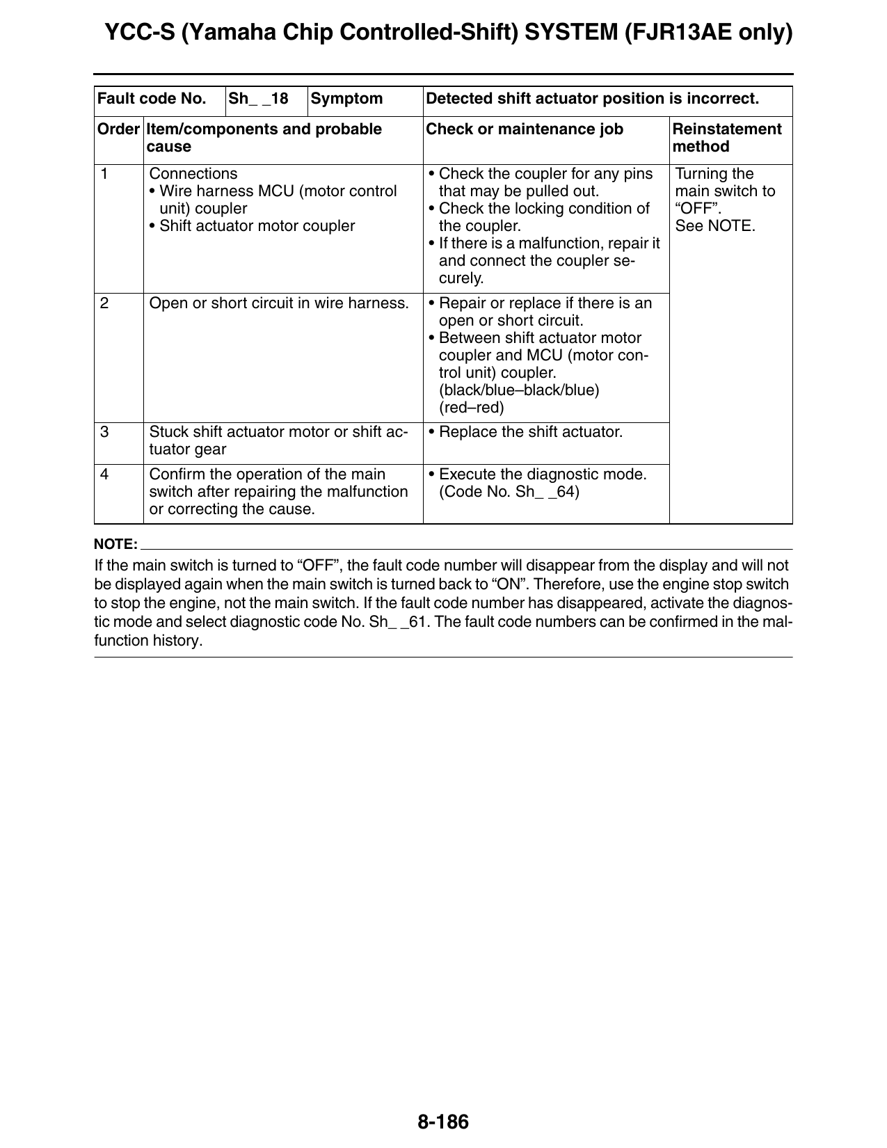
YCC-S (Yamaha Chip Controlled-Shift) SYSTEM (FJR13AE only)
Fault code No. Sh_ _18 Symptom Detected shift actuator position is incorrect.
Order Item/components and probable Check or maintenance job Reinstatement
cause method
1 Connections • Check the coupler for any pins Turning the
• Wire harness MCU (motor control that may be pulled out. main switch to
unit) coupler • Check the locking condition of “OFF”.
• Shift actuator motor coupler the coupler. See NOTE.
• If there is a malfunction, repair it
and connect the coupler se-
curely.
2 Open or short circuit in wire harness. • Repair or replace if there is an
open or short circuit.
• Between shift actuator motor
coupler and MCU (motor con-
trol unit) coupler.
(black/blue–black/blue)
(red–red)
3 Stuck shift actuator motor or shift ac- • Replace the shift actuator.
tuator gear
4 Confirm the operation of the main • Execute the diagnostic mode.
switch after repairing the malfunction (Code No. Sh_ _64)
or correcting the cause.
NOTE:
If the main switch is turned to “OFF”, the fault code number will disappear from the display and will not
be displayed again when the main switch is turned back to “ON”. Therefore, use the engine stop switch
to stop the engine, not the main switch. If the fault code number has disappeared, activate the diagnos-
tic mode and select diagnostic code No. Sh_ _61. The fault code numbers can be confirmed in the mal-
function history.
8-186
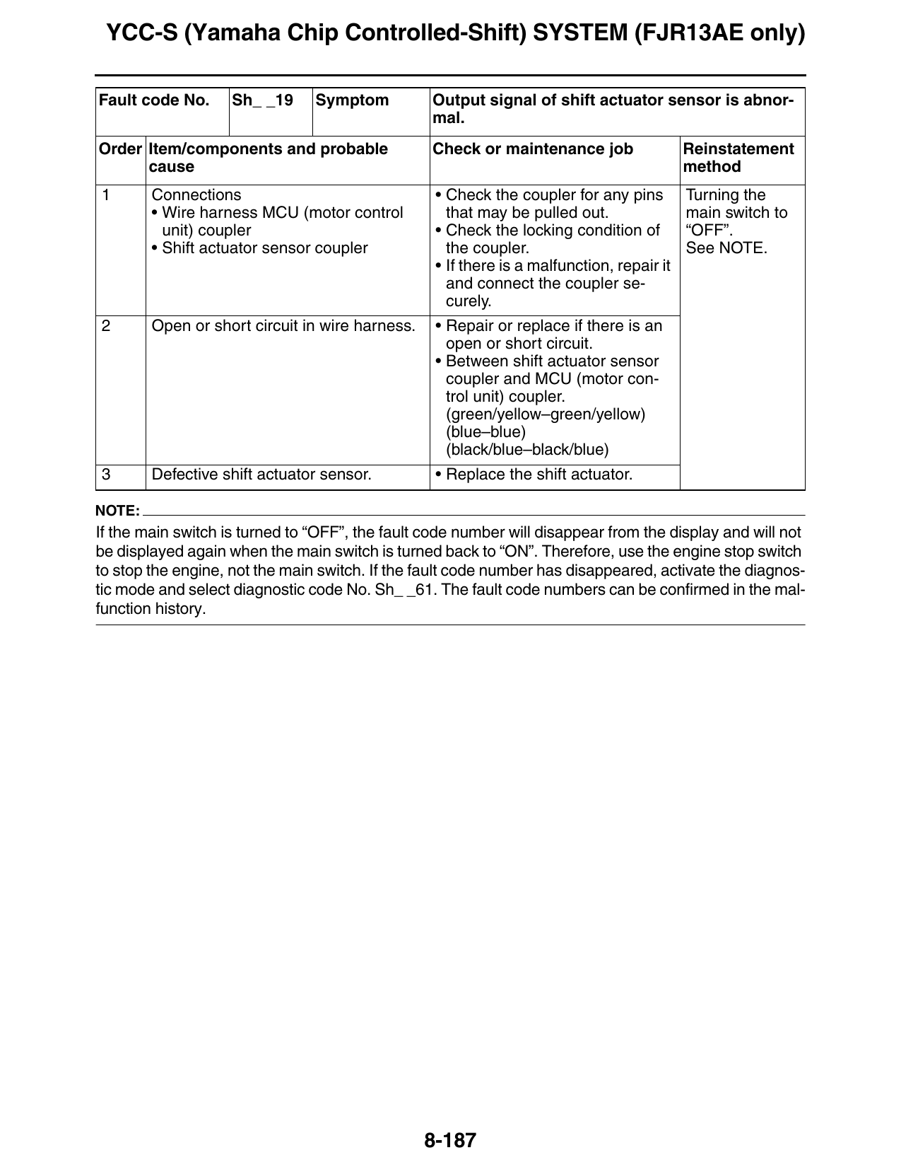
YCC-S (Yamaha Chip Controlled-Shift) SYSTEM (FJR13AE only)
Fault code No. Sh_ _19 Symptom Output signal of shift actuator sensor is abnor-
mal.
Order Item/components and probable Check or maintenance job Reinstatement
cause method
1 Connections • Check the coupler for any pins Turning the
• Wire harness MCU (motor control that may be pulled out. main switch to
unit) coupler • Check the locking condition of “OFF”.
• Shift actuator sensor coupler the coupler. See NOTE.
• If there is a malfunction, repair it
and connect the coupler se-
curely.
2 Open or short circuit in wire harness. • Repair or replace if there is an
open or short circuit.
• Between shift actuator sensor
coupler and MCU (motor con-
trol unit) coupler.
(green/yellow–green/yellow)
(blue–blue)
(black/blue–black/blue)
3 Defective shift actuator sensor. • Replace the shift actuator.
NOTE:
If the main switch is turned to “OFF”, the fault code number will disappear from the display and will not
be displayed again when the main switch is turned back to “ON”. Therefore, use the engine stop switch
to stop the engine, not the main switch. If the fault code number has disappeared, activate the diagnos-
tic mode and select diagnostic code No. Sh_ _61. The fault code numbers can be confirmed in the mal-
function history.
8-187
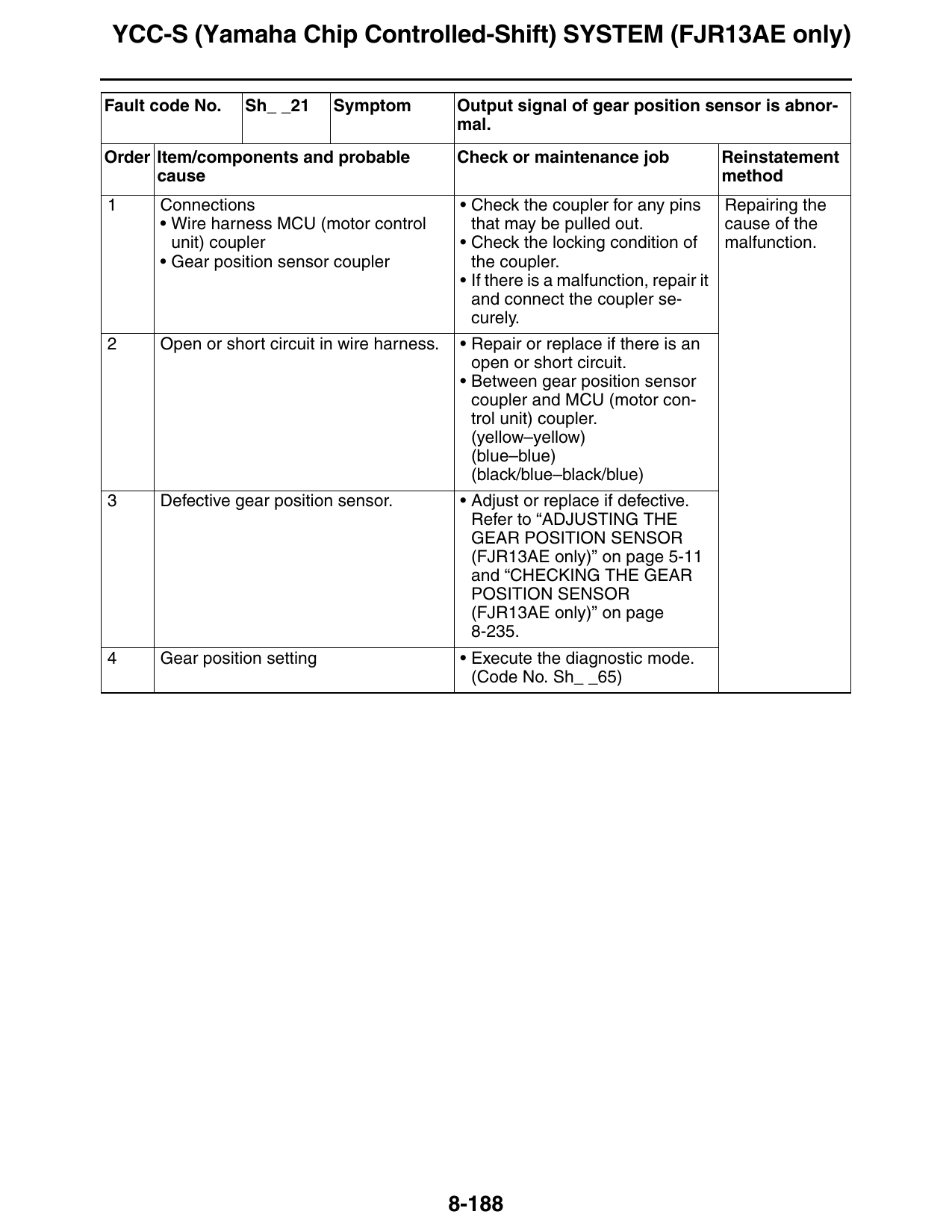
YCC-S (Yamaha Chip Controlled-Shift) SYSTEM (FJR13AE only)
Fault code No. Sh_ _21 Symptom Output signal of gear position sensor is abnor-
mal.
Order Item/components and probable Check or maintenance job Reinstatement
cause method
1 Connections • Check the coupler for any pins Repairing the
• Wire harness MCU (motor control that may be pulled out. cause of the
unit) coupler • Check the locking condition of malfunction.
• Gear position sensor coupler the coupler.
• If there is a malfunction, repair it
and connect the coupler se-
curely.
2 Open or short circuit in wire harness. • Repair or replace if there is an
open or short circuit.
• Between gear position sensor
coupler and MCU (motor con-
trol unit) coupler.
(yellow–yellow)
(blue–blue)
(black/blue–black/blue)
3 Defective gear position sensor. • Adjust or replace if defective.
Refer to “ADJUSTING THE
GEAR POSITION SENSOR
(FJR13AE only)” on page 5-11
and “CHECKING THE GEAR
POSITION SENSOR
(FJR13AE only)” on page
8-235.
4 Gear position setting • Execute the diagnostic mode.
(Code No. Sh_ _65)
8-188
YCC-S (Yamaha Chip Controlled-Shift) SYSTEM (FJR13AE only)
Fault code No. Sh_ _22 Symptom Output signal of foot shift switch is abnormal.
Order Item/components and probable Check or maintenance job Reinstatement
cause method
1 Connections • Check the coupler for any pins Repairing the
• Wire harness MCU (motor control that may be pulled out. cause of the
unit) coupler • Check the locking condition of malfunction.
• Foot shift switch coupler the coupler.
• If there is a malfunction, repair it
and connect the coupler se-
curely.
2 Open or short circuit in wire harness • Repair or replace if there is an
and/or sub-lead 2. open or short circuit.
• Between foot shift switch cou-
pler and MCU (motor control
unit) coupler.
(orange/red–orange/black)
(blue–blue)
(black/blue–black/blue)
3 Defective foot shift switch. • Adjust or replace if defective.
Refer to “ADJUSTING THE
FOOT SHIFT SWITCH” on
page 5-70 and “CHECKING
THE FOOT SHIFT SWITCH
(FJR13AE only)” on page
8-235.
Fault code No. Sh_ _23 Symptom No input signal from sidestand switch.
Order Item/components and probable Check or maintenance job Reinstatement
cause method
1 Connections • Check the coupler for any pins Repairing the
• Wire harness MCU (motor control that may be pulled out. cause of the
unit) coupler • Check the locking condition of malfunction.
the coupler.
• If there is a malfunction, repair it
and connect the coupler se-
curely.
2 Open circuit in wire harness. • Repair or replace if there is an
open circuit.
• Between sidestand switch cou-
pler and MCU (motor control
unit) coupler.
(blue/green–blue/green)
3 Defective sidestand switch. • Check and replace if defective.
Refer to “CHECKING THE
SWITCHES” on page 8-211.
8-189
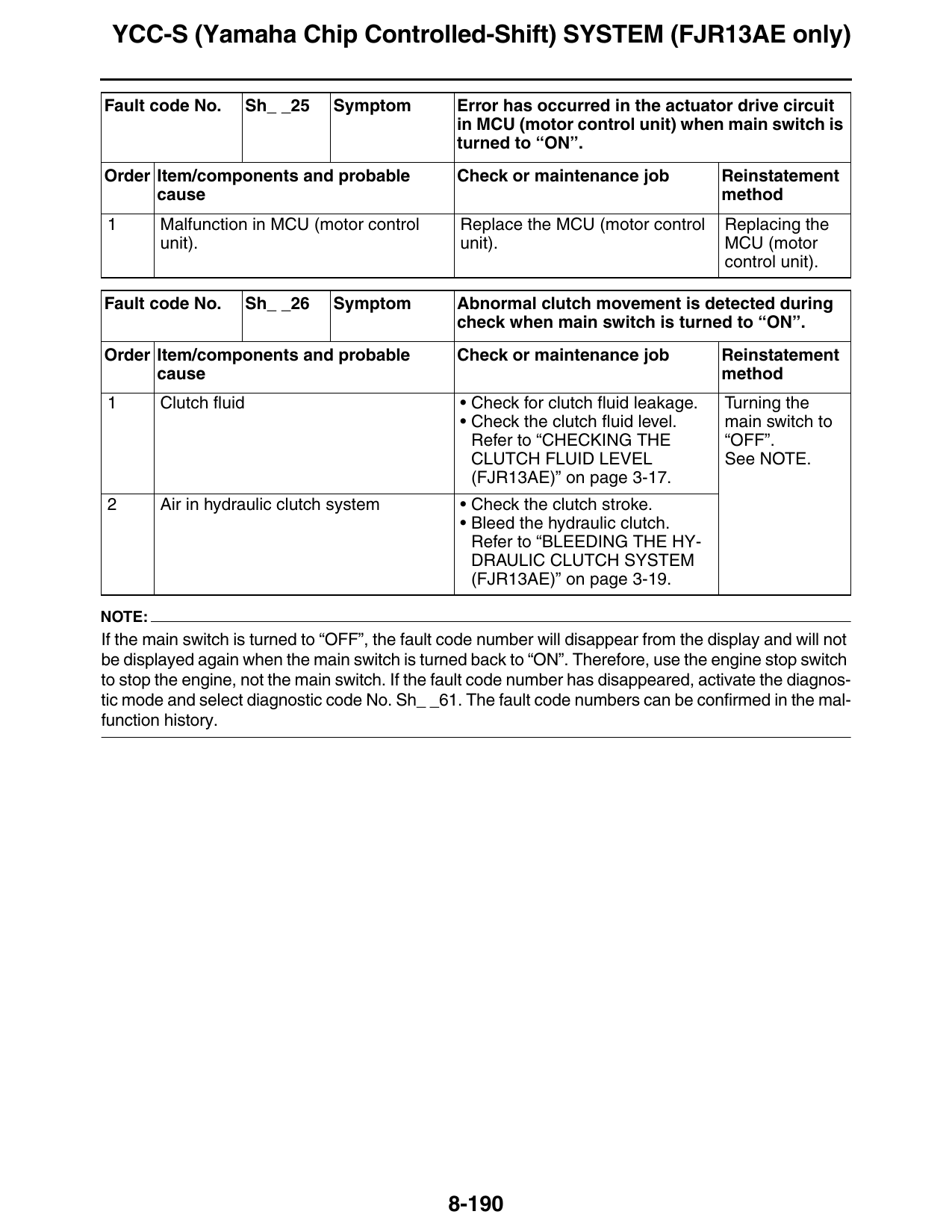
YCC-S (Yamaha Chip Controlled-Shift) SYSTEM (FJR13AE only)
Fault code No. Sh_ _25 Symptom Error has occurred in the actuator drive circuit
in MCU (motor control unit) when main switch is
turned to “ON”.
Order Item/components and probable Check or maintenance job Reinstatement
cause method
1 Malfunction in MCU (motor control Replace the MCU (motor control Replacing the
unit). unit). MCU (motor
control unit).
Fault code No. Sh_ _26 Symptom Abnormal clutch movement is detected during
check when main switch is turned to “ON”.
Order Item/components and probable Check or maintenance job Reinstatement
cause method
1 Clutch fluid • Check for clutch fluid leakage. Turning the
• Check the clutch fluid level. main switch to
Refer to “CHECKING THE “OFF”.
CLUTCH FLUID LEVEL See NOTE.
(FJR13AE)” on page 3-17.
2 Air in hydraulic clutch system • Check the clutch stroke.
• Bleed the hydraulic clutch.
Refer to “BLEEDING THE HY-
DRAULIC CLUTCH SYSTEM
(FJR13AE)” on page 3-19.
NOTE:
If the main switch is turned to “OFF”, the fault code number will disappear from the display and will not
be displayed again when the main switch is turned back to “ON”. Therefore, use the engine stop switch
to stop the engine, not the main switch. If the fault code number has disappeared, activate the diagnos-
tic mode and select diagnostic code No. Sh_ _61. The fault code numbers can be confirmed in the mal-
function history.
8-190
YCC-S (Yamaha Chip Controlled-Shift) SYSTEM (FJR13AE only)
Fault code No. Sh_ _27 Symptom Diagnosis mode is activated at engine start-up.
Order Item/components and probable Check or maintenance job Reinstatement
cause method
1 YCC-S test coupler • Check that the test coupler Turning the
adapter is not connected. main switch to
Refer to “DIAGNOSTIC MODE” “OFF”.
on page 8-175. See NOTE.
2 Short circuit in wire harness. • Repair or replace if there is a
short circuit.
• Between YCC-S test coupler
and MCU (motor control unit)
coupler.
(blue/yellow–blue/yellow)
NOTE:
If the main switch is turned to “OFF”, the fault code number will disappear from the display and will not
be displayed again when the main switch is turned back to “ON”. Therefore, use the engine stop switch
to stop the engine, not the main switch. If the fault code number has disappeared, activate the diagnos-
tic mode and select diagnostic code No. Sh_ _61. The fault code numbers can be confirmed in the mal-
function history.
Fault code No. Sh_ _31 Symptom Engine speed signal is abnormal.
Order Item/components and probable Check or maintenance job Reinstatement
cause method
1 Connections • Check the coupler for any pins Repairing the
• Wire harness MCU (motor control that may be pulled out. cause of the
unit) coupler • Check the locking condition of malfunction.
• Wire harness ECU coupler the coupler.
• If there is a malfunction, repair it
and connect the coupler se-
curely.
2 Open or short circuit in wire harness. • Repair or replace if there is an
open or short circuit.
• Between ECU coupler and
MCU (motor control unit) cou-
pler.
(yellow/black–yellow/black)
8-191
YCC-S (Yamaha Chip Controlled-Shift) SYSTEM (FJR13AE only)
Fault code No. Sh_ _32 Symptom YCC-S speed sensor signal is abnormal.
Order Item/components and probable Check or maintenance job Reinstatement
cause method
1 Connections • Check the coupler for any pins Turning the
• Wire harness MCU (motor control that may be pulled out. main switch to
unit) coupler • Check the locking condition of “OFF”.
• YCC-S speed sensor coupler the coupler. See NOTE.
• If there is a malfunction, repair it
and connect the coupler se-
curely.
2 Open or short circuit in wire harness. • Repair or replace if there is an
open or short circuit.
• Between YCC-S speed sensor
coupler and MCU (motor con-
trol unit) coupler.
(white/yellow–white/yellow)
(blue–blue)
(black/blue–black/blue)
3 Defective YCC-S speed sensor. • Replace if detective.
Refer to “CHECKING THE
YCC-S SPEED SENSOR
(FJR13AE only)” on page
8-234.
NOTE:
If the main switch is turned to “OFF”, the fault code number will disappear from the display and will not
be displayed again when the main switch is turned back to “ON”. Therefore, use the engine stop switch
to stop the engine, not the main switch. If the fault code number has disappeared, activate the diagnos-
tic mode and select diagnostic code No. Sh_ _61. The fault code numbers can be confirmed in the mal-
function history.
Fault code No. Sh_ _34 Symptom TPS (throttle position sensor) signal is abnor-
mal.
Order Item/components and probable Check or maintenance job Reinstatement
cause method
1 Connections • Check the coupler for any pins Repairing the
• Wire harness MCU (motor control that may be pulled out. cause of the
unit) coupler • Check the locking condition of malfunction.
• Wire harness ECU coupler the coupler.
• If there is a malfunction, repair it
and connect the coupler se-
curely.
2 Open or short circuit in wire harness. • Repair or replace if there is an
open or short circuit.
• Between ECU coupler and
MCU (motor control unit) cou-
pler.
(yellow/blue–yellow/blue)
8-192
YCC-S (Yamaha Chip Controlled-Shift) SYSTEM (FJR13AE only)
Fault code No. Sh_ _35 Symptom Start switch signal is abnormal.
Order Item/components and probable Check or maintenance job Reinstatement
cause method
1 Connections • Check the coupler for any pins Repairing the
• Wire harness MCU (motor control that may be pulled out. cause of the
unit) coupler • Check the locking condition of malfunction.
• Relay unit coupler the coupler.
• Right handlebar switch coupler • If there is a malfunction, repair it
and connect the coupler se-
curely.
2 Open or short circuit in wire harness • Repair or replace if there is an
and/or front cowling wire harness. open or short circuit.
• Between right handlebar switch
coupler and relay unit coupler.
(white/blue–white/blue)
• Between relay unit coupler and
MCU (motor control unit) cou-
pler.
(blue/white–blue/white)
3 Defective relay unit. • Check and replace relay unit.
Refer to “CHECKING THE RE-
LAYS” on page 8-221.
4 Defective start switch. • Check and replace right handle-
bar switch.
Refer to “CHECKING THE
SWITCHES” on page 8-211.
Fault code No. Sh_ _36 Symptom Output signal of clutch actuator sensor is ab-
normal.
Order Item/components and probable Check or maintenance job Reinstatement
cause method
1 Connections • Check the coupler for any pins Repairing the
• Wire harness MCU (motor control that may be pulled out. cause of the
unit) coupler • Check the locking condition of malfunction.
• Clutch actuator sensor coupler the coupler.
• If there is a malfunction, repair it
and connect the coupler se-
curely.
2 Open or short circuit in wire harness • Repair or replace if there is an
and/or sub-lead 1. open or short circuit.
• Between clutch actuator sen-
sor coupler and MCU (motor
control unit) coupler.
(orange–orange)
(orange/green–orange/green)
(blue–blue)
(black/blue–black/blue)
3 Defective clutch actuator sensor. • Replace clutch actuator.
8-193
YCC-S (Yamaha Chip Controlled-Shift) SYSTEM (FJR13AE only)
Fault code No. Sh_ _37 Symptom Power supply to clutch or shift actuator motor is
abnormal.
Order Item/components and probable Check or maintenance job Reinstatement
cause method
1 Connections • Check the coupler for any pins Turning the
• Wire harness MCU (motor control that may be pulled out. main switch to
unit) coupler • Check the locking condition of “OFF”.
• Clutch actuator motor coupler the coupler. See NOTE.
• Shift actuator motor coupler • If there is a malfunction, repair it
and connect the coupler se-
curely.
2 Open or short circuit in wire harness. • Repair or replace if there is an
open or short circuit.
• Between clutch actuator motor
coupler and MCU (motor con-
trol unit) coupler.
(black/white–black/white)
(red/white–red/white)
• Between shift actuator motor
coupler and MCU (motor con-
trol unit) coupler.
(black/blue–black/blue)
(red–red)
3 Defective clutch or shift actuator mo- • Replace the clutch actuator or
tor. shift actuator.
NOTE:
If the main switch is turned to “OFF”, the fault code number will disappear from the display and will not
be displayed again when the main switch is turned back to “ON”. Therefore, use the engine stop switch
to stop the engine, not the main switch. If the fault code number has disappeared, activate the diagnos-
tic mode and select diagnostic code No. Sh_ _61. The fault code numbers can be confirmed in the mal-
function history.
8-194
YCC-S (Yamaha Chip Controlled-Shift) SYSTEM (FJR13AE only)
Fault code No. Sh_ _38 Symptom Malfunction of hand shift lever switch (shift up
or shift down).
Order Item/components and probable Check or maintenance job Reinstatement
cause method
1 Connections • Check the coupler for any pins Repairing the
• Wire harness MCU (motor control that may be pulled out. cause of the
unit) coupler • Check the locking condition of malfunction.
• Hand shift switch coupler the coupler.
• If there is a malfunction, repair it
and connect the coupler se-
curely.
2 Open or short circuit in wire harness. • Repair or replace if there is an
open or short circuit.
• Between hand shift switch cou-
pler and MCU (motor control
unit) coupler.
(orange/white–orange/white)
(orange/black–orange/black)
(green/red–green/red)
(green/black–green/black)
3 Defective hand shift lever switch (shift • Replace hand shift switch.
up or shift down). Refer to “CHECKING THE
SWITCHES” on page 8-211.
Fault code No. Sh_ _39 Symptom Ignition timing retard output signal is abnormal.
Order Item/components and probable Check or maintenance job Reinstatement
cause method
1 Connections • Check the coupler for any pins Repairing the
• Wire harness MCU (motor control that may be pulled out. cause of the
unit) coupler • Check the locking condition of malfunction.
• Wire harness ECU coupler the coupler.
• If there is a malfunction, repair it
and connect the coupler se-
curely.
2 Open or short circuit in wire harness. • Repair or replace if there is an
open or short circuit.
• Between ECU coupler and
MCU (motor control unit) cou-
pler.
(light green–light green)
8-195
YCC-S (Yamaha Chip Controlled-Shift) SYSTEM (FJR13AE only)
Fault code No. Sh_ _41 Symptom Coolant temperature sensor signal is abnormal.
Order Item/components and probable Check or maintenance job Reinstatement
cause method
1 Connections • Check the coupler for any pins Repairing the
• Wire harness MCU (motor control that may be pulled out. cause of the
unit) coupler • Check the locking condition of malfunction.
• Wire harness ECU coupler the coupler.
• If there is a malfunction, repair it
and connect the coupler se-
curely.
2 Open or short circuit in wire harness. • Repair or replace if there is an
open or short circuit.
• Between ECU coupler and
MCU (motor control unit) cou-
pler.
(yellow/blue–yellow/blue)
Fault code No. Sh_ _42 Symptom Communication between ECU and multi-func-
tion meter is abnormal.
Order Item/components and probable Check or maintenance job Reinstatement
cause method
1 Connections • Check the coupler for any pins Repairing the
• Wire harness MCU (motor control that may be pulled out. cause of the
unit) coupler • Check the locking condition of malfunction.
• YCC-S speed sensor coupler the coupler.
• If there is a malfunction, repair it
and connect the coupler se-
curely.
2 Open or short circuit in wire harness. • Repair or replace if there is an
open or short circuit.
• Between YCC-S speed sensor
coupler and MCU (motor con-
trol unit) coupler.
(yellow/blue–yellow/blue)
8-196
YCC-S (Yamaha Chip Controlled-Shift) SYSTEM (FJR13AE only)
Fault code No. Sh_ _43 Symptom Communication between MCU (motor control
unit) and ABS ECU is abnormal.
Order Item/components and probable Check or maintenance job Reinstatement
cause method
1 Connections • Check the coupler for any pins Repairing the
• Wire harness MCU (motor control that may be pulled out. cause of the
unit) coupler • Check the locking condition of malfunction.
• ABS ECU coupler the coupler.
• If there is a malfunction, repair it
and connect the coupler se-
curely.
2 Open or short circuit in wire harness. • Repair or replace if there is an
open or short circuit.
• Between ABS ECU coupler and
MCU (motor control unit) cou-
pler.
(brown/black–brown/black)
Fault code No. Sh_ _44 Symptom Clutch actuator sensor signal is abnormal.
Order Item/components and probable Check or maintenance job Reinstatement
cause method
1 Defective clutch actuator sensor. • Replace clutch actuator. Turning the
2 Confirm the operation of the main • Execute the diagnostic mode. main switch to
switch after repairing the malfunction (Code No. Sh_ _63) “OFF”.
or correcting the cause. See NOTE.
NOTE:
If the main switch is turned to “OFF”, the fault code number will disappear from the display and will not
be displayed again when the main switch is turned back to “ON”. Therefore, use the engine stop switch
to stop the engine, not the main switch. If the fault code number has disappeared, activate the diagnos-
tic mode and select diagnostic code No. Sh_ _61. The fault code numbers can be confirmed in the mal-
function history.
8-197
YCC-S (Yamaha Chip Controlled-Shift) SYSTEM (FJR13AE only)
Fault code No. Sh_ _45 Symptom Shift operation and gear position do not match.
Order Item/components and probable Check or maintenance job Reinstatement
cause method
1 Shift rod • Check the shift rod pin hole lo- Turning the
cation. main switch to
• Check the shift rod groove loca- “OFF”.
tion. See NOTE.
• Adjust or replace if defective.
Refer to “CHECKING THE
SHIFT ROD” on page 5-69 and
“INSTALLING THE SHIFT AC-
TUATOR” on page 5-71.
2 Defective shift actuator. • Replace shift actuator.
3 Confirm the operation of the main • Execute the diagnostic mode.
switch after repairing the malfunction (Code No. Sh_ _64)
or correcting the cause.
NOTE:
If the main switch is turned to “OFF”, the fault code number will disappear from the display and will not
be displayed again when the main switch is turned back to “ON”. Therefore, use the engine stop switch
to stop the engine, not the main switch. If the fault code number has disappeared, activate the diagnos-
tic mode and select diagnostic code No. Sh_ _61. The fault code numbers can be confirmed in the mal-
function history.
Fault code No. Sh_ _46 Symptom Engine speed and gear position sensor signal
do not match while vehicle is driven.
Order Item/components and probable Check or maintenance job Reinstatement
cause method
1 Gear position setting. • Execute the diagnostic mode. Turning the
(Code No. Sh_ _65) main switch to
“OFF”.
See NOTE.
NOTE:
If the main switch is turned to “OFF”, the fault code number will disappear from the display and will not
be displayed again when the main switch is turned back to “ON”. Therefore, use the engine stop switch
to stop the engine, not the main switch. If the fault code number has disappeared, activate the diagnos-
tic mode and select diagnostic code No. Sh_ _61. The fault code numbers can be confirmed in the mal-
function history.
8-198
YCC-S (Yamaha Chip Controlled-Shift) SYSTEM (FJR13AE only)
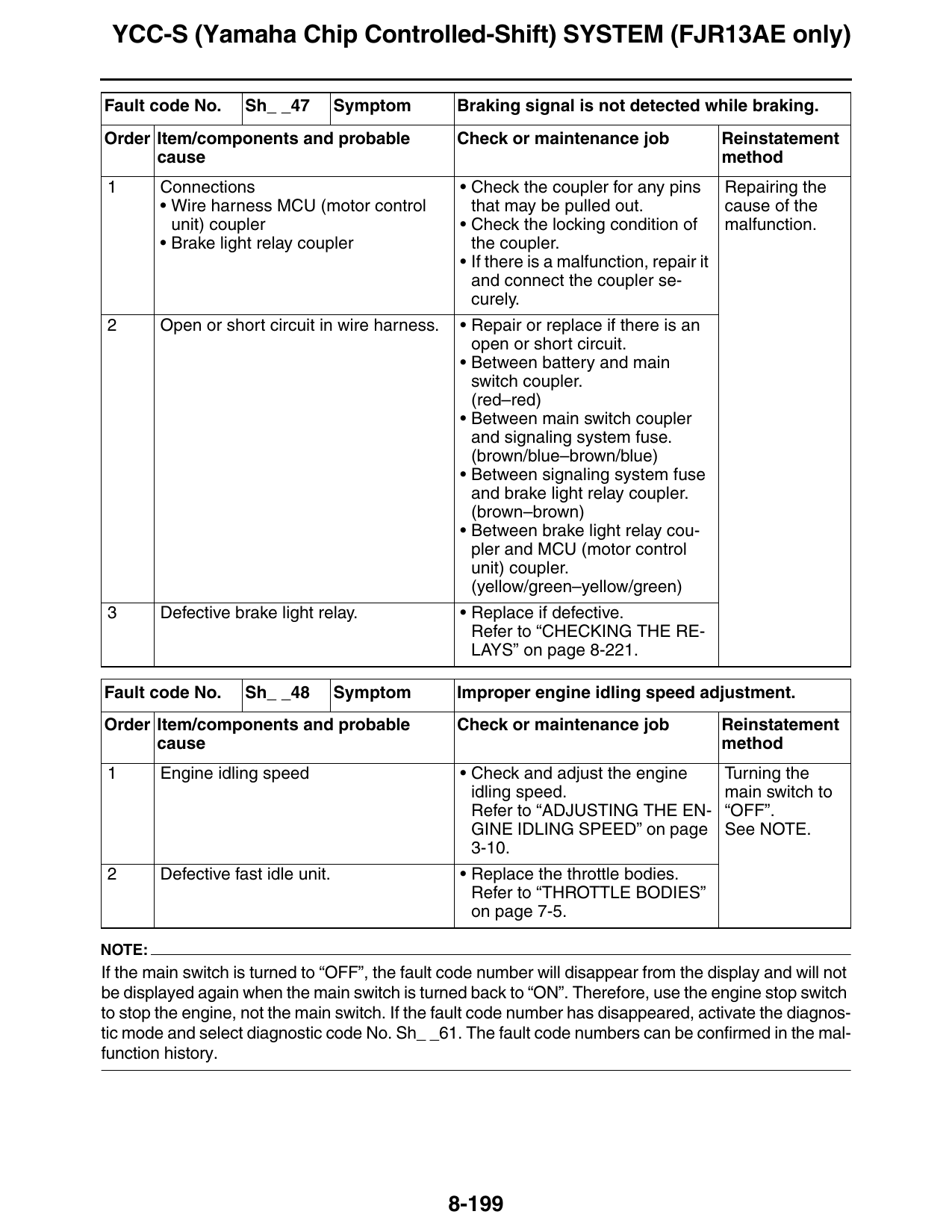
Fault code No. Sh_ _47 Symptom Braking signal is not detected while braking.
Order Item/components and probable Check or maintenance job Reinstatement
cause method
1 Connections • Check the coupler for any pins Repairing the
• Wire harness MCU (motor control that may be pulled out. cause of the
unit) coupler • Check the locking condition of malfunction.
• Brake light relay coupler the coupler.
• If there is a malfunction, repair it
and connect the coupler se-
curely.
2 Open or short circuit in wire harness. • Repair or replace if there is an
open or short circuit.
• Between battery and main
switch coupler.
(red–red)
• Between main switch coupler
and signaling system fuse.
(brown/blue–brown/blue)
• Between signaling system fuse
and brake light relay coupler.
(brown–brown)
• Between brake light relay cou-
pler and MCU (motor control
unit) coupler.
(yellow/green–yellow/green)
3 Defective brake light relay. • Replace if defective.
Refer to “CHECKING THE RE-
LAYS” on page 8-221.
Fault code No. Sh_ _48 Symptom Improper engine idling speed adjustment.
Order Item/components and probable Check or maintenance job Reinstatement
cause method
1 Engine idling speed • Check and adjust the engine Turning the
idling speed. main switch to
Refer to “ADJUSTING THE EN- “OFF”.
GINE IDLING SPEED” on page See NOTE.
3-10.
2 Defective fast idle unit. • Replace the throttle bodies.
Refer to “THROTTLE BODIES”
on page 7-5.
NOTE:
If the main switch is turned to “OFF”, the fault code number will disappear from the display and will not
be displayed again when the main switch is turned back to “ON”. Therefore, use the engine stop switch
to stop the engine, not the main switch. If the fault code number has disappeared, activate the diagnos-
tic mode and select diagnostic code No. Sh_ _61. The fault code numbers can be confirmed in the mal-
function history.
8-199
YCC-S (Yamaha Chip Controlled-Shift) SYSTEM (FJR13AE only)
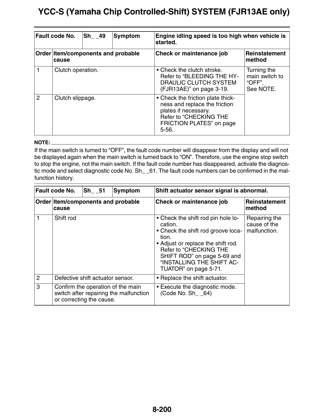
Fault code No. Sh_ _49 Symptom Engine idling speed is too high when vehicle is
started.
Order Item/components and probable Check or maintenance job Reinstatement
cause method
1 Clutch operation. • Check the clutch stroke. Turning the
Refer to “BLEEDING THE HY- main switch to
DRAULIC CLUTCH SYSTEM “OFF”.
(FJR13AE)” on page 3-19. See NOTE.
2 Clutch slippage. • Check the friction plate thick-
ness and replace the friction
plates if necessary.
Refer to “CHECKING THE
FRICTION PLATES” on page
5-56.
NOTE:
If the main switch is turned to “OFF”, the fault code number will disappear from the display and will not
be displayed again when the main switch is turned back to “ON”. Therefore, use the engine stop switch
to stop the engine, not the main switch. If the fault code number has disappeared, activate the diagnos-
tic mode and select diagnostic code No. Sh_ _61. The fault code numbers can be confirmed in the mal-
function history.
Fault code No. Sh_ _51 Symptom Shift actuator sensor signal is abnormal.
Order Item/components and probable Check or maintenance job Reinstatement
cause method
1 Shift rod • Check the shift rod pin hole lo- Repairing the
cation. cause of the
• Check the shift rod groove loca- malfunction.
tion.
• Adjust or replace the shift rod.
Refer to “CHECKING THE
SHIFT ROD” on page 5-69 and
“INSTALLING THE SHIFT AC-
TUATOR” on page 5-71.
2 Defective shift actuator sensor. • Replace the shift actuator.
3 Confirm the operation of the main • Execute the diagnostic mode.
switch after repairing the malfunction (Code No. Sh_ _64)
or correcting the cause.
8-200
YCC-S (Yamaha Chip Controlled-Shift) SYSTEM (FJR13AE only)
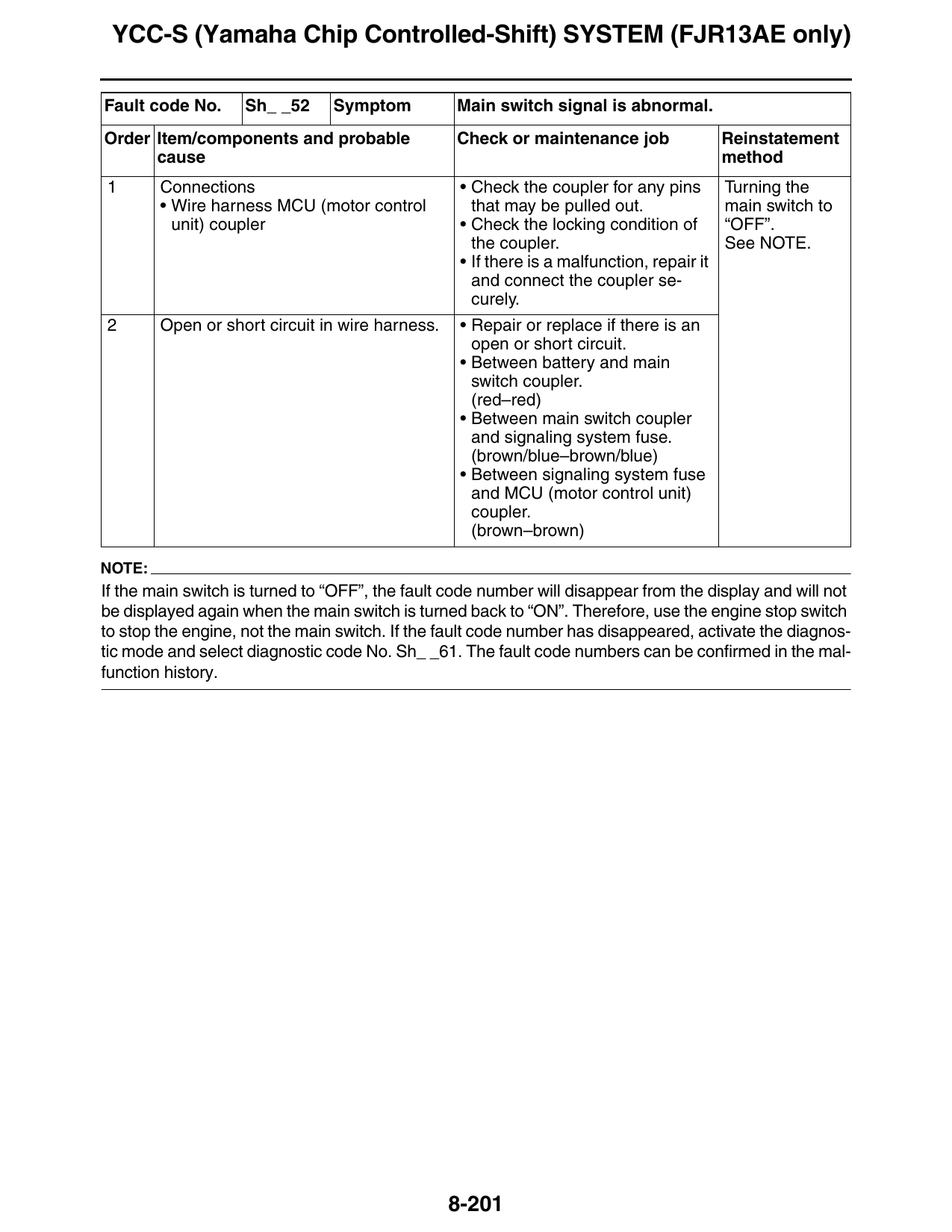
Fault code No. Sh_ _52 Symptom Main switch signal is abnormal.
Order Item/components and probable Check or maintenance job Reinstatement
cause method
1 Connections • Check the coupler for any pins Turning the
• Wire harness MCU (motor control that may be pulled out. main switch to
unit) coupler • Check the locking condition of “OFF”.
the coupler. See NOTE.
• If there is a malfunction, repair it
and connect the coupler se-
curely.
2 Open or short circuit in wire harness. • Repair or replace if there is an
open or short circuit.
• Between battery and main
switch coupler.
(red–red)
• Between main switch coupler
and signaling system fuse.
(brown/blue–brown/blue)
• Between signaling system fuse
and MCU (motor control unit)
coupler.
(brown–brown)
NOTE:
If the main switch is turned to “OFF”, the fault code number will disappear from the display and will not
be displayed again when the main switch is turned back to “ON”. Therefore, use the engine stop switch
to stop the engine, not the main switch. If the fault code number has disappeared, activate the diagnos-
tic mode and select diagnostic code No. Sh_ _61. The fault code numbers can be confirmed in the mal-
function history.
8-201
YCC-S (Yamaha Chip Controlled-Shift) SYSTEM (FJR13AE only)
8-202