🏍️ FJR1300 RP13

Checking The ABS Motor Relay

Fragment manuala — str. 694

📋 Tekst do skopiowania / wyszukiwania
ELECTRICAL COMPONENTS
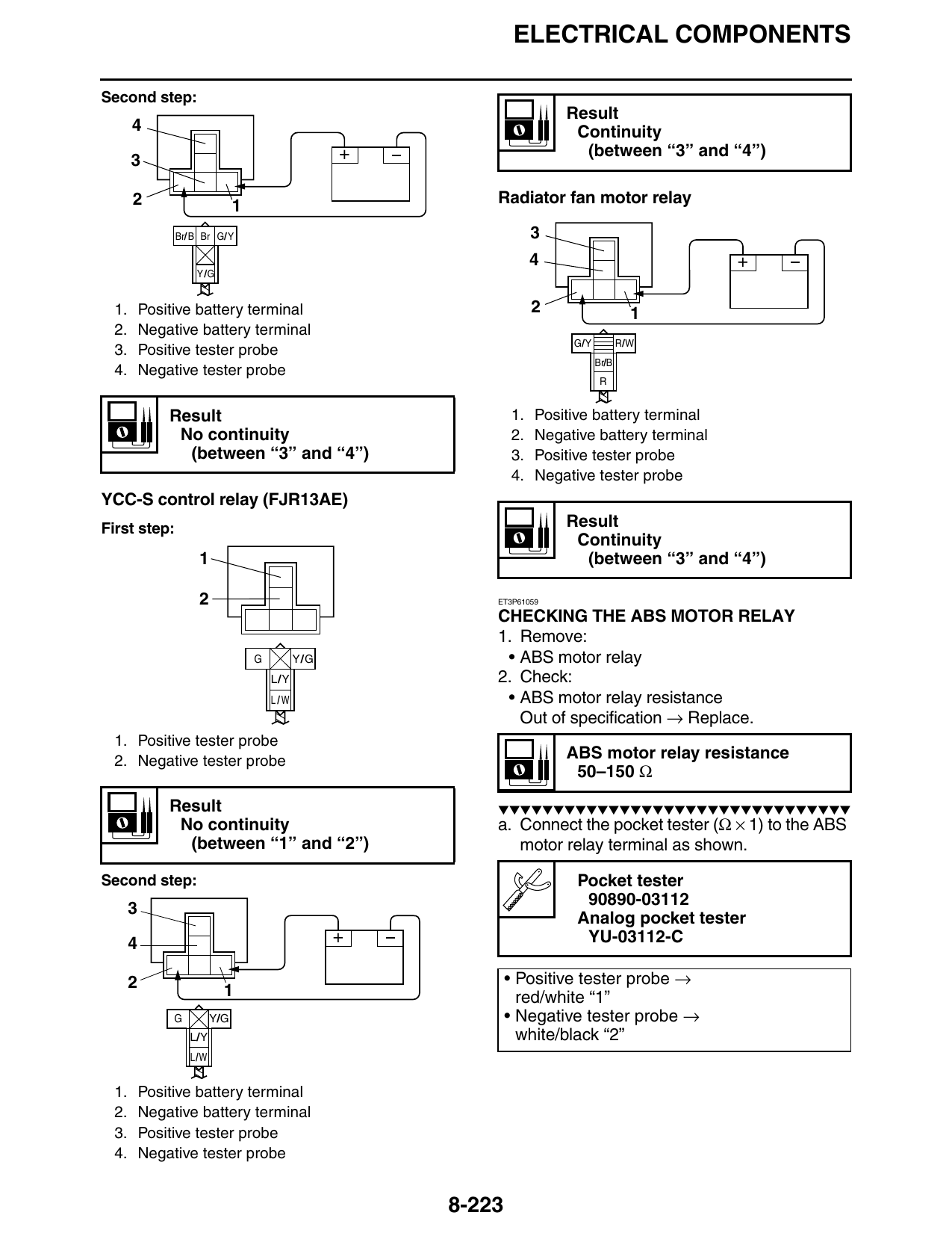
Second step:
                                                                     Result
    4                                                                 Continuity
                                                 +                     (between “3” and “4”)

    2                        1                           Radiator fan motor relay

              Br/ B Br G/Y                                      3
                                                                4                           +
                  Y /G

 1. Positive battery terminal                                   2                   1
 2. Negative battery terminal
                                                                     G/Y          R/W
 3. Positive tester probe
                                                                           Br/B
 4. Negative tester probe
                                                                            R

          Result                                             1. Positive battery terminal
           No continuity                                     2. Negative battery terminal
            (between “3” and “4”)                            3. Positive tester probe
                                                             4. Negative tester probe
YCC-S control relay (FJR13AE)
First step:                                                          Result
                                                                      Continuity
                  1                                                    (between “3” and “4”)

                  2                                      ET3P61059

                                                         CHECKING THE ABS MOTOR RELAY
                                                         1. Remove:
                                 G         Y/G            • ABS motor relay
                                     L/Y                 2. Check:
                                     L/W                  • ABS motor relay resistance
                                                            Out of specification → Replace.
 1. Positive tester probe
 2. Negative tester probe                                            ABS motor relay resistance
                                                                      50–150 Ω

          Result                                         ▼▼▼▼▼▼▼▼▼▼▼▼▼▼▼▼▼▼▼▼▼▼▼▼▼▼▼▼▼▼▼▼
           No continuity                                 a. Connect the pocket tester (Ω × 1) to the ABS
            (between “1” and “2”)                           motor relay terminal as shown.

Second step:                                                          Pocket tester
                                                                       90890-03112
                                                                      Analog pocket tester
    4                                            +                     YU-03112-C

    2                                                        • Positive tester probe →
                         1                                     red/white “1”
          G            Y/G                                   • Negative tester probe →
                 L/Y                                           white/black “2”
                 L/W

 1. Positive battery terminal
 2. Negative battery terminal
 3. Positive tester probe
 4. Negative tester probe

                                                     8-223