Checking The Relays
Fragment manuala — str. 692–693
📋 Tekst do skopiowania / wyszukiwania
ELECTRICAL COMPONENTS
Relay unit (starting circuit cut-off relay)
Recommended lubricant
Dielectric grease
10.Install:
• Front cowling right inner panel 1
Refer to “GENERAL CHASSIS” on page 4-1.
EAS28040
CHECKING THE RELAYS
Check each switch for continuity with the pocket
tester. If the continuity reading is incorrect, re-
place the relay. 1. Positive battery terminal
2. Negative battery terminal
Pocket tester 3. Positive tester probe
90890-03112 4. Negative tester probe
Analog pocket tester
YU-03112-C
Result
Continuity
1. Disconnect the relay from the wire harness.
(between “3” and “4”)
2. Connect the pocket tester (Ω × 1) and battery
(12 V) to the relay terminals as shown.
Check the relay operation. Relay unit (fuel pump relay)
Out of specification → Replace.
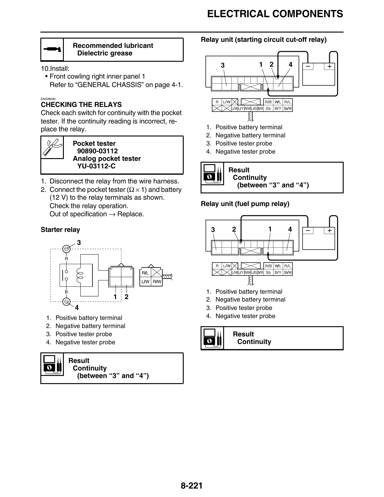
Starter relay
R
R/L
L/W R/W
B 1. Positive battery terminal
1 2 2. Negative battery terminal
4 3. Positive tester probe
1. Positive battery terminal 4. Negative tester probe
2. Negative battery terminal
3. Positive tester probe Result
4. Negative tester probe Continuity
Result
Continuity
(between “3” and “4”)
8-221
ELECTRICAL COMPONENTS
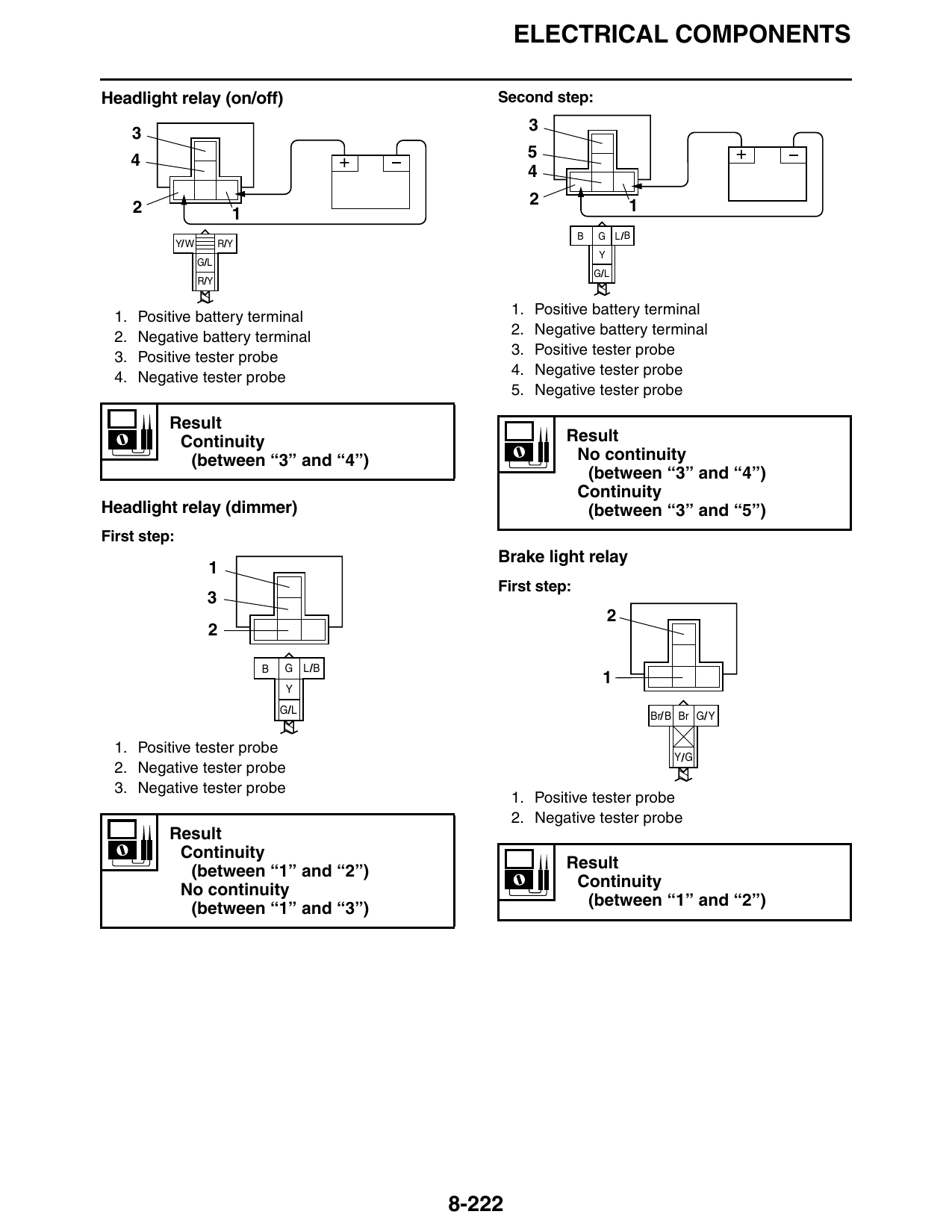
Headlight relay (on/off) Second step:
3 3
4 5 +
+
2 2 1
B G L/B
Y/W R/Y
Y
G/L
G/L
R/Y
1. Positive battery terminal 1. Positive battery terminal
2. Negative battery terminal
2. Negative battery terminal
3. Positive tester probe 3. Positive tester probe
4. Negative tester probe 4. Negative tester probe
5. Negative tester probe
Result
Continuity Result
(between “3” and “4”) No continuity
(between “3” and “4”)
Continuity
Headlight relay (dimmer) (between “3” and “5”)
First step:
Brake light relay
First step:
B G L/B
Y
G/L
Br/ B Br G/Y
1. Positive tester probe
Y/G
2. Negative tester probe
3. Negative tester probe
1. Positive tester probe
2. Negative tester probe
Result
Continuity
(between “1” and “2”) Result
No continuity Continuity
(between “1” and “3”) (between “1” and “2”)
8-222